 Facebook
 Google
 GitHub
 Linkedin
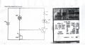
My knowledge is very limited and I learn in baby steps. I have built a LM317 power supply. I assembled on a breadboard the attached circuit. The LED did not light, battery got warm and I think also the NPN. I tried again using alligator clip jumpers with no luck. I tried the LED with resistor and that works. On my DMM I checked the NPN and it reads 22 HFE. I tried backwards and it reads 1 HFE so I think I have my c, b and e correct. I assume the NPN is just a 'gate' which permits c to go to e and that the amount of current 'supplied' to b will determine how much the gate opens. I assume the current from c goes to e and b also goes to e. My salvaged LDR reads from 40k to 200 ohms dependent on light intensity. I believe that a resistor just limits current but doesn't do anything with the voltage.
1) Are my assumptions correct?
2) What does R2 do? Can I eliminate it?
3) Are there any additonal tests that I can do to confirm NPN is still good?
4) What does "VEBO 9V in the specs mean?
5) If resistance of LDR drops below R1 (390 ohms) does 'gate' still open?
If suggestions/changes are made on the circuit I would appreciate also the why/how, in basic laymans terms, so I can try to understand how things work.
Attachments
-
 277 KB Views: 66
 -
 277 KB Views: 61


