Facebook
 Google
 GitHub
 Linkedin
hi,
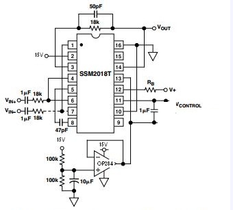
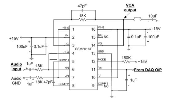
Currently im trying to make an addition circuit with allow me to use only +15V inside of + - 15V. I using the circuit as shown on the SSM2018T datasheet as shown below..
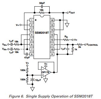
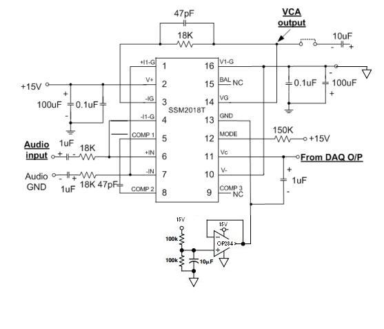
I compare both OP176 and OP284 datasheet and decided to use the circuit in SSM2018T datasheet but OP284 was used instead of OP176. Today i went to test on the OP284 circuit, The output wave was a DC with 7.5V ( till to the Voltage divider from the 2 100K resister..) Then i connect the output to pin 13 as shown on the above picture. Originally, SSM2018T required a +-15V, if not the ic will start to get very hot because its cant sweep on negative part/positive part.after connecting pin 16 to gnd. When i switch on the power, i touch the IC to make sure that its not getting too hot..After a few sec, the IC didnt heat up so i think that its ok to continue my test. I pump in a 300Hz, amp of 0.05 to pin 6...I check on the output of SSM2018T (pin14) i get a DC line with a few MV (sorry forgot the value)..and when i try to set some value (using labview) to the Vcontrol. The output remain the same.. At 1st i tot that the op284 will some how create a negative prt by offset the DC to the middle of +15V (7.5v)..So positive swing from 7.5V to 15V and negative swing from 7.5V to 0V..But after seeing the output of SSM2018T, i got lost and not sure what to do next..Is it that the way of my thinking is wrong, or the circuit shdn't be design this way? Sorry for all the top wordy...
Currently im trying to make an addition circuit with allow me to use only +15V inside of + - 15V. I using the circuit as shown on the SSM2018T datasheet as shown below..
I compare both OP176 and OP284 datasheet and decided to use the circuit in SSM2018T datasheet but OP284 was used instead of OP176. Today i went to test on the OP284 circuit, The output wave was a DC with 7.5V ( till to the Voltage divider from the 2 100K resister..) Then i connect the output to pin 13 as shown on the above picture. Originally, SSM2018T required a +-15V, if not the ic will start to get very hot because its cant sweep on negative part/positive part.after connecting pin 16 to gnd. When i switch on the power, i touch the IC to make sure that its not getting too hot..After a few sec, the IC didnt heat up so i think that its ok to continue my test. I pump in a 300Hz, amp of 0.05 to pin 6...I check on the output of SSM2018T (pin14) i get a DC line with a few MV (sorry forgot the value)..and when i try to set some value (using labview) to the Vcontrol. The output remain the same.. At 1st i tot that the op284 will some how create a negative prt by offset the DC to the middle of +15V (7.5v)..So positive swing from 7.5V to 15V and negative swing from 7.5V to 0V..But after seeing the output of SSM2018T, i got lost and not sure what to do next..Is it that the way of my thinking is wrong, or the circuit shdn't be design this way? Sorry for all the top wordy...
Last edited: