Hi All,
I'm hoping some of you help me out.
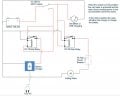
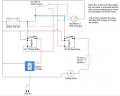
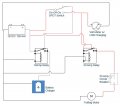
I want to make a power box for my trolling motor. Using a weatherproof case, I want to put a battery, charger and a combo voltmeter/USB charger inside. On the outside would be power connections, the voltmeter display and an on-off-on switch. I want to use the switch to switch between charging mode and trolling mode. The idea being when I want to use it to power the trolling motor, I plug the motor into a power connection, set the switch to one of the "ons" and when I want to charge, I connect 110v to a separate connector and set the switch to the other "on" and let it charge.
The trolling motor is 50 AMP draw. So I think I need a relay and a circuit breaker. The charger is a 10 AMP draw, so i think I need a relay for that too. I made a wiring diagram (attached). I'm kindly asking for any input anyone is willing to provide.
My questions are:
Is my diagram accurate?
Am I doing this right?
Thanks!
Dane
Budd Lake, NJ
I'm hoping some of you help me out.
I want to make a power box for my trolling motor. Using a weatherproof case, I want to put a battery, charger and a combo voltmeter/USB charger inside. On the outside would be power connections, the voltmeter display and an on-off-on switch. I want to use the switch to switch between charging mode and trolling mode. The idea being when I want to use it to power the trolling motor, I plug the motor into a power connection, set the switch to one of the "ons" and when I want to charge, I connect 110v to a separate connector and set the switch to the other "on" and let it charge.
The trolling motor is 50 AMP draw. So I think I need a relay and a circuit breaker. The charger is a 10 AMP draw, so i think I need a relay for that too. I made a wiring diagram (attached). I'm kindly asking for any input anyone is willing to provide.
My questions are:
Is my diagram accurate?
Am I doing this right?
Thanks!
Dane
Budd Lake, NJ
Attachments
-
 43.3 KB Views: 25
Last edited by a moderator:
")