I have tried several ocillators circuits I have seen online and when i connect them to the oscilloscope they all show dying not smooth oscillations and flat lines. What wrong with circuit above ?.
Unless there is a buffer stage, the capacitance of the oscilloscope probe cable could be killing the oscillations before you have a chance to see them.
Unless there is a buffer stage, the capacitance of the oscilloscope probe cable could be killing the oscillations before you have a chance to see them.
Fix: Use a X10 scope probe that's good for your intended frequency to reduce the capacitive loading of the scope.
I built a similar "transmitters" about 55 years ago. No need for all those parts. I omitted the emitter resistor and capacitor, tying the emitter directly to the battery's negative terminal (usually used a 9 volt transistor radio battery). Omitted the resistor from the base to ground and used a 100k or 47k resistor from the base to the battery's positive terminal. A ceramic capacitor (.01 or .001 uf) across the battery terminals usually helps.
Make sure your transistor has a high enough Ft (it's in the data sheet). There are many good transistors that are not useful for RF.
With and RF choke in the collector the oscillator will oscillate at the crystal's fundamental frequency. If you replace the choke with a resonant tank you can get it to oscillate at an overtone (harmonic). We were using crystals from Citizen's Band walkie-talkies with an untuned choke for a collector load and although you could hear the transmitter's harmonics on the Citizen's Band but most of the transmitter power was around 9 MHz.
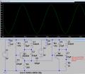
Here is a transmitter for the FM broadcast band that is nearly foolproof (no, do not add an antenna yet):
For the inductor about 8 turns of #24 wire on a pencil. Adjust the tuning range by physically distorting the coil's dimentions. You can use a 5 pf capacitor instead of the adjustable capacitor you want and only tune the transmitter by deforming the coil. Low level audio across C4 will cause frequency modulation. All of the capacitors other than C3 ceramic. The transistor can also be another small signal transistor with an Ft of 200 MHz or greater - even some 2N2222's can do that!
Fix: Use a X10 scope probe that's good for your intended frequency to reduce the capacitive loading of the scope.
I built a similar "transmitters" about 55 years ago. No need for all those parts. I omitted the emitter resistor and capacitor, tying the emitter directly to the battery's negative terminal (usually used a 9 volt transistor radio battery). Omitted the resistor from the base to ground and used a 100k or 47k resistor from the base to the battery's positive terminal. A ceramic capacitor (.01 or .001 uf) across the battery terminals usually helps.
Make sure your transistor has a high enough Ft (it's in the data sheet). There are many good transistors that are not useful for RF.
With and RF choke in the collector the oscillator will oscillate at the crystal's fundamental frequency. If you replace the choke with a resonant tank you can get it to oscillate at an overtone (harmonic). We were using crystals from Citizen's Band walkie-talkies with an untuned choke for a collector load and although you could hear the transmitter's harmonics on the Citizen's Band but most of the transmitter power was around 9 MHz.
Here is a transmitter for the FM broadcast band that is nearly foolproof (no, do not add an antenna yet): View attachment 284051
For the inductor about 8 turns of #24 wire on a pencil. Adjust the tuning range by physically distorting the coil's dimentions. You can use a 5 pf capacitor instead of the adjustable capacitor you want and only tune the transmitter by deforming the coil. Low level audio across C4 will cause frequency modulation. All of the capacitors other than C3 ceramic. The transistor can also be another small signal transistor with an Ft of 200 MHz or greater - even some 2N2222's can do that!
On my FM transmitter:
1) The RF frequency changed when the battery voltage wore down so I added a 5V low-dropout regulator.
2) The RF frequency changed when anything moved toward or away from the antenna so I added an RF output stage (powered from 9V for lots of illegal output power) to isolate the oscillator from the antenna.
3) The FM de-emphasis in all FM radios caused sounds to be muffled so I added matching audio pre-emphasis like all FM radio stations use.
Here is an RF circuit tweaked in a simulation for low levels of RF harmonics and the highest output power:
There's a lot or garbage on the internet especially with RF circuits that will never work. I used to build these single transistor and two transistor 'bugs' back in the 70's. Not sure why you're bothering with a scope as attaching anything to such a simple circuit will load it and stop it from working. Being a transmitter why not just use a receiver to pick it up. The audio quality with an electret is stunning as is the unlimited deviation!
Have fun experimenting, it's a great circuit to start you out in RF.
Just as a little encouragement, it doesn't have to be very neat, though sort leads in the RF section are important, and no PC board is really need either. I have been using the transmitter in the photo below for about three months -it sends audio from my desktop computer to a nearby FM radio - after many years the built-in audio on my computer had faded considerably : -)
This circuit was thrown together to test the pre-emphasis, but these old ears cannot tell when the pre-emphasis is working and when it is not.
I used to use xtals but became too expensive so got someone to write some software for the AD9833, works for the 9834 too so I'm good for frequency generation!
Re the oscillator 'issue', being L/C it'll wander all over the place but at VHF provided you used a stout coil (pref silver plated) and a good quality cap and use WFM you won't notice the drift too much as long as you don't touch the circuit. Then just use a buffer as has been shown in the LTSpice schematic. The best design uses 3 trans, audio, osc and amp if you want the ultimate! wo going to a PLL or Xtal multiplier chain.
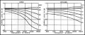
My modern hearing aids fixed my old ears and added selectable noise reduction and compression for very loud sounds (motorcycles?). At my age of 77 now, my hearing loss at 8kHz is probably about -77dB which is the limit for my hearing aids.
Here is a graph of typical hearing loss vs age:
Stents in my heart fixed a heart attack and hearing aids fixed my hearing. Oh yeah, my eyes had very bad cataracts that are fixed with internal lenses. New dentures work well. I barely notice some arthritis. I can still run fast with my dog. I am young again.
Stents in my heart fixed a heart attack and hearing aids fixed my hearing. Oh yeah, my eyes had very bad cataracts that are fixed with internal lenses. New dentures work well. I barely notice some arthritis. I can still run fast with my dog. I am young again.
There's a lot or garbage on the internet especially with RF circuits that will never work. I used to build these single transistor and two transistor 'bugs' back in the 70's. Not sure why you're bothering with a scope as attaching anything to such a simple circuit will load it and stop it from working. Being a transmitter why not just use a receiver to pick it up. The audio quality with an electret is stunning as is the unlimited deviation!
Have fun experimenting, it's a great circuit to start you out in RF.
 Facebook
 Google
 GitHub
 Linkedin


")


