Facebook
 Google
 GitHub
 Linkedin
Please teach me.
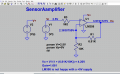
When you setup an LM358 op amp as a voltage amplifier why is it that you use an inverting amp rather than an non inverting amp?
I have one of these ACS712 current sensors and want to amplify it's output 1.5 times so I initially used a non inverting amp but it made the opamp output voltage go lower. (?) Yet, the inverting amp will amplify the voltage accordingly. The knowledge I have on "inverting and non inverting" is limited to in phase or out of phase but not getting what's going on beyond that. -- big thanks