Noise when switching an AC solinoid value.

Thread Starter

Gokulakrishnan_1234

Joined Feb 20, 2025
1
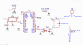
I'm trying to create a digital water flow meter with limit control using an Arduino Nano. The flow meter has a reed switch that closes and opens for every 10 liters of water flow. To count the total liters consumed, I've connected the reed switch to an interrupt pin on the Arduino. To cut off the water flow, I've used a 230V AC solenoid valve.

The problem is that when the 230V AC is not connected, the liter count is accurate. However, when the AC voltage is turned on, the count increases randomly when I try to switch the solenoid valve. The noise is not coming from the relay coil but from the load (solenoid valve).

What are the possible ways to resolve this issue?


I've enclosed the circuit diagram
 

Attachments

ericgibbs

Joined Jan 29, 2010
21,391
hi 1234,
Welcome to AAC.
One point is the relay coil should have a suppression diode in parallel.

You should also add a 100R and a 100n mains voltage rated, capacitor in series across the solenoid coil.
E
 

MrChips

Joined Oct 2, 2009
34,628
Welcome to AAC!

Here are a few suggestions you can try.

1) Put a 0.1 μF capacitor across pin-30 (Vin) and pin-4 (GND) of U1. There should already be a capacitor there if this is a properly made Arduino board.

2) D2 should have a pull-up resistor, 1k - 4.7kΩ. Put a 10 - 100 nF capacitor from D2 to GND. If this does not solve the problem, try higher values such as 1 μF.

3) Put a snubber diode across pins 3 and 4 of U2. Pay attention to the direction of the diode. The cathode goes to Vcc.

4) Move the solenoid as far away from the circuit as possible. Try putting a 47nF /400VAC capacitor across the solenoid.
 

MaxHeadRoom

Joined Jul 18, 2013
30,562
I tend to stay away from AC operated solenoids if possible, the only advantage they have is at switch on time, after this they are not as reliable as a DC version.
Most available are 24vdc but there are higher voltage ones around.
 

crutschow

Joined Mar 14, 2008
38,322
If none of the above suggestions work, you might try using a shielded twisted-pair wire from the AC source to the solenoid.

Do you know the current and inductance characteristics of the solenoid?
 
Last edited:

MisterBill2

Joined Jan 23, 2018
27,186
Several problems are obvious. First, the flow switch output should not be grounded, but rather just wires to the digital input. Second, contact bounce in the 230volt control relay, third, the DC supply for the relay coil should not have any point common with the processor circuit. Isolation is very helpful.
 
Last edited:

Ian0

Joined Aug 7, 2020
13,097
What value of pullup resistor have you used on the reed switch? Or are you relying on the one in the processor?
 

twohats

Joined Oct 28, 2015
607
Hi,
You have +5v going to V in.
Try +5v to 5v (pin 27).
I've found that a mains filter from a scrap washing machine works well on mains relays and solenoids.
Good luck.......
 

MisterBill2

Joined Jan 23, 2018
27,186
On top of the other things, the opto-isolator is not allowed to isolate! Use a separate supply for the relay coil power and do not tie the output of the opto-isolator back to the processor power. In addition, the solenoid valve wiring should be well away from the rest of the wiring.
 

MisterBill2

Joined Jan 23, 2018
27,186
The TS already has a 230 volts AC solenoid valve, And with the number of connected sources showing in the supplied circuit, it seems reasonable to not spend another $50 (USD) for another water valve. Consider that each of the three loops are tied directly to the processor common connection. So there are a lot of places to provide isolation.
 
Top