Noise reduction connecting PCB to USB

Thread Starter

jd96jack

Joined Apr 28, 2021
6
Hi! After producing multiple different PCB designs of a board for controlling a stepper motor, I noticed something that I cannot explain.
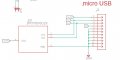
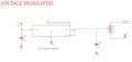
The boards are in general powered through 12 volts, then a voltage regulator brings the voltage from 12 to 5 V and another one from 5 to 3.3 V. Stepper drivers and microcontroller use 3V3 logic. Moreover there is a USB port for communication with the microcontroller.

I noticed (with different drivers, such as drv8825 and tmc2208), that motors tend to be less noisy and more reliable as soon as the USB is connected. I noticed with the oscilloscope that noise is heavily reduced when I connect the board to computer through USB compared to only 12 V power supply (stable lab power supply, with big decoupling electrolytic caps).
Could it be that connecting the USB I'm creating a more robust ground connection and it reduces the ground bounce? (I have two ground planes and a separate one for insulating the driver ground, connected to the others in one point).

I'm not so experienced and I couldn't find relevant literature addressing the problem.
Spit out all the hypothesis/theories may spring to your mind, thank you very much :)
 

dl324

Joined Mar 30, 2015
16,845
It would be helpful if you posted a block diagram showing how things are hooked up to power. In particular how grounds are connected, maximum currents in the wires, wire guages, where decoupling caps are placed and their sizes. Though I'm loath to ask for them, pictures might also be helpful.

  1. How much current do the motors draw?
  2. How many motors are operating when you observe this noise and reliability problem?
  3. What is the nature of this noise? Audible or electronic?
  4. What is the nature of the reliability problem?
  5. What is the USB cable connected to? How is that device powered?
  6. Do you have separate grounds for the digital components and the motor controllers that are connected at a single point?
 

Thread Starter

jd96jack

Joined Apr 28, 2021
6
It would be helpful if you posted a block diagram showing how things are hooked up to power. In particular how grounds are connected, maximum currents in the wires, wire guages, where decoupling caps are placed and their sizes. Though I'm loath to ask for them, pictures might also be helpful.

  1. How much current do the motors draw?
  2. How many motors are operating when you observe this noise and reliability problem?
  3. What is the nature of this noise? Audible or electronic?
  4. What is the nature of the reliability problem?
  5. What is the USB cable connected to? How is that device powered?
  6. Do you have separate grounds for the digital components and the motor controllers that are connected at a single point?
Thank you very much for your answer. I made a small diagram showing the big picture and then I post the schematics of the specific parts in depth.
Let me now answer your questions:
  • One board controls one motor and the motor draws up to 1 A, but in general, I set the current to 0.5 A.
  • With the DRV8825 the noise was audible and electric. In the new design, the DRV8825 has been replaced with a TMC2208 (also because of the noise), and it is at least quieter.
  • The reliability problem in particular concerns the VREF we set from the controller to set the current flowing in the motor coils. Namely, even if from the controller we are sending a clean analog signal, the driver many times fails in setting the right current and outputs random currents (or the max current). This leads to loss of torque in the motors, as such unreliable for any application.
  • The USB cable (you can see how it is connected to the board in the pictures uploaded) is connected to a computer that is connected to the power line.
  • Yes, as I show in the diagram, we have separated grounds that are connected through a soldered pad.
Hope to have clarified the context! Looking forward to hearing your guess
 

Attachments

Thread Starter

jd96jack

Joined Apr 28, 2021
6
. What is the current rating of the 12V to 5V regulator ?
In the latest design, we got rid of the 12-5 V stage and now we go straight into 3.3V. The voltage regulator we are using has an output current rating of 300 mA. Consider that the driver is completely alimented from 12 V power supply, so that current should only control the ucontroller. Thanks for your answer!
 

BobTPH

Joined Jun 5, 2013
8,812
Sounds to me like your 12V supply is not grounded to your mains, whereas the USB is. Most low voltage supplies are isolated.

Bb
 

Thread Starter

jd96jack

Joined Apr 28, 2021
6
Sounds to me like your 12V supply is not grounded to your mains, whereas the USB is. Most low voltage supplies are isolated.

Bb
Good guess but unfortunately I tried connecting the - terminal to the GND terminal in the power supply but it doesn't actually fix the issue
 

BGS_eng

Joined May 19, 2021
1
Sounds to me like your 12V supply is not grounded to your mains, whereas the USB is. Most low voltage supplies are isolated.

Bb
thats what i was thinking......once the usb gets connected, the shield is connected to mains GND....while the lab PSU isnt.....but will have a GND/EARTH connection
 

PadMasterson

Joined Jan 19, 2021
63
Not sure if you have a picture of the PCB showing placement of the components and routing, but I would hope you have the ground/return path for the motors/drivers not crossing any of the USB or other digital input or traces carrying digital signals. What types of caps and where are they located in respect to the uP and motor driver, etc. I do PCB design as a living and I can't tell you how important it is to make sure returns and any signal traces on the digital side, do not cross or get in the areas of the motor drive lines. Splitting the plane is not necessary as long as you keep the two separate from each other. Good luck...
 
Top