Facebook
 Google
 GitHub
 Linkedin
Hi,
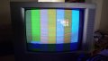
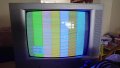
I would really appreciate some expertise here. I am trying to convert an RGBHV signal from a GBS-8220 board modified for GBS control, to composite video. The GBS is outputting a 15Khz signal and I am using the sync combiner circuit described here: https://www.retrorgb.com/building-a-passive-sync-combiner.html. I have previously tested this with the RGB lines on an old RGBS monitor and a Scart TV and it displayed perfectly.
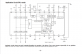
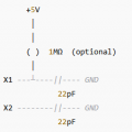
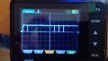
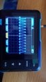
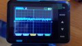
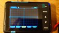
I have followed the example circuit detailed in the datasheet here: https://www.alldatasheet.com/datasheet-pdf/pdf/46644/SONY/CXA1645P.html (PAL version). But the result is no output from the composite pin. Have tested with a oscilloscope and it's a flat line (see screenshot). I have verified the RGB signals and they do register on the oscillioscope - measure around 0.9v with the multimeter on the input pin. Further debugging shows the two vcc pins are both getting 5v, the composite sync signal is around 2.7v. I have a 4.43 MHZ crystal oscillator connected between the SCIN pin (6) and ground. Specifically one of these: https://www.aliexpress.com/item/1005002600232112.html - I think that's the correct setup for PAL.
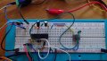
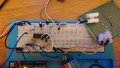
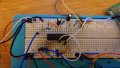
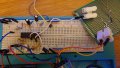
I have attached photos of everything connected on the breadboard. I appreciate these are not the easiest things to follow but I really don't know how else to show the setup. If anyone has any suggestions please let me know. I'm at a loss as to where to go with this otherwise.
Thanks in advance.
I would really appreciate some expertise here. I am trying to convert an RGBHV signal from a GBS-8220 board modified for GBS control, to composite video. The GBS is outputting a 15Khz signal and I am using the sync combiner circuit described here: https://www.retrorgb.com/building-a-passive-sync-combiner.html. I have previously tested this with the RGB lines on an old RGBS monitor and a Scart TV and it displayed perfectly.
I have followed the example circuit detailed in the datasheet here: https://www.alldatasheet.com/datasheet-pdf/pdf/46644/SONY/CXA1645P.html (PAL version). But the result is no output from the composite pin. Have tested with a oscilloscope and it's a flat line (see screenshot). I have verified the RGB signals and they do register on the oscillioscope - measure around 0.9v with the multimeter on the input pin. Further debugging shows the two vcc pins are both getting 5v, the composite sync signal is around 2.7v. I have a 4.43 MHZ crystal oscillator connected between the SCIN pin (6) and ground. Specifically one of these: https://www.aliexpress.com/item/1005002600232112.html - I think that's the correct setup for PAL.
I have attached photos of everything connected on the breadboard. I appreciate these are not the easiest things to follow but I really don't know how else to show the setup. If anyone has any suggestions please let me know. I'm at a loss as to where to go with this otherwise.
Thanks in advance.
Attachments
-
 1.8 MB Views: 7
 -
 2.2 MB Views: 7
 -
 1.8 MB Views: 9
 -
 2.1 MB Views: 9