NF8 - SPDT Sugar Cube Realy footprint problem

Thread Starter

mishra87

Joined Jan 17, 2016
1,034
Hi All ,

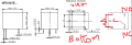
I am using NF8 SPDT relay for my circuit.
But I have confusion regarding C,NC & NO connections.

Could anybody confirm if I made correct connection because once PCB gets manufacture it would be difficult for me.

Relay is sugar cube realy !!!

My assumption in PCB design is lef TOP is connected to Common pin of relay. I assume lef TOP is NC pin and it is not connected anywhere because it's internally connected with C.

I assume Bottom left in PCB is NO pin of relay .

Pls confirm my assumption is true .

Regards ,
 

Attachments

MaxHeadRoom

Joined Jul 18, 2013
28,617
PDF: Top left and bottom left is the relay coil. Underside view.
In the NF8-001E the bottom right is the N.C. contact, top right is the N.O. contact, the one between the coil terminals is the contact Common.
BTW, as you can see, the N.C. contact is not really doing anything!
Max.
 
Last edited:

MaxHeadRoom

Joined Jul 18, 2013
28,617
The last sentence of my post was regarding the JPG of the PCT, that only the N.O. contact is relevant.
The N.C. contact and common share the same foil trace.!
Max.
 

Thread Starter

mishra87

Joined Jan 17, 2016
1,034
The last sentence of my post was regarding the JPG of the PCT, that only the N.O. contact is relevant.
The N.C. contact and common share the same foil trace.!
Max.
Yes , you are correct .
My question was ...

Are my PCB relay footprint matching the footprint given NF8 datasheet because once we manufacture the PCB it would be difficult to do rework. In datasheet bottom view of relay is given.

I had confusion if it correct or not.
 

Thread Starter

mishra87

Joined Jan 17, 2016
1,034
If that is the foil side shown, then it does appear correct.
Max.
Thank you so much for your reply!!

Actually NF8 relay land pattern shows it bottom view but in PCB i have to make footprint TOP view of relay.
You can have look of signal flow in attached image.
The NC pin is not connected to anywhere left floating because its internally connected to relay.

My confusion is that if my assumption is not correct and NC and NO are swapped then there will be problem in board testing.
Still i am not sure if it connected correctly.

Still PCB is to be released because of this confusion.
 

Attachments

narkeleptk

Joined Mar 11, 2019
558
if the datasheet means you are holding it upside down and looking at the bottom (and not looking at the bottom through the top).... and on your pcb we are looking down on from the top as if we where holding it.... then it appears backwards to me so I understand your confusion.
 

Thread Starter

mishra87

Joined Jan 17, 2016
1,034
if the datasheet means you are holding it upside down and looking at the bottom (and not looking at the bottom through the top).... and on your pcb we are looking down on from the top as if we where holding it.... then it appears backwards to me so I understand your confusion.

Could you correct the attached image and send back to me ...
 

MaxHeadRoom

Joined Jul 18, 2013
28,617
It appears simple to me, the footprint is shown from the bottom, the relay will be in the opposite side of the board and rotated 180°.
If you have the relay at hand it is a very simple to confirm.
Max.
 

Thread Starter

mishra87

Joined Jan 17, 2016
1,034
It appears simple to me, the footprint is shown from the bottom, the relay will be in the opposite side of the board and rotated 180°.
If you have the relay at hand it is a very simple to confirm.
Max.
I don't have physical part with my hand that's main problem.

But as you told it should be 180 degree rotated .

Then NC and NO should be swapped.
Isn't it .???
 

narkeleptk

Joined Mar 11, 2019
558
I'm not really following here but I'm no expert at this stuff so take my opinion lightly.

If the relay is to be mounted on top of the pcb shown and the datasheet for the needed relay is showing us the bottom of that relay (like its being held upside down), then by flipping it over and placing it in the pcb it appears to me the NC is where TS wants the NO.


I think, Im suggesting the relay will be on TOP of the PCB and Max is suggesting the relay will be on the BOTTOM of the pcb, in which case we are saying the same thing and it depends on which side you will be mounting the relay.
 

MaxHeadRoom

Joined Jul 18, 2013
28,617
Another take, is if the view is the component side and the relay is also on this side of the board, and the blue trace is on the reverse (under) side, then the contact is shown wrong, opposite to what it should be.
Max.
 
Top