New Tremolo design.....

Thread Starter

Fluxor1964

Joined Jun 11, 2015
182
The 555 has a triangle wave spanning the middle I/3 of Vcc at the timing capacitor, if you buffer this for enough current to drive a filament bulb, it rounds it off a fair bit.

An LDR is by far the best variable resistance element, but I haven't seen many listed since RoHS. A couple of years back I ordered a few packets from China - whether they've clamped down on that...........
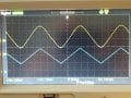
I bought a pack of LDRs here in the US from RadioShack.
 

Alec_t

Joined Sep 17, 2013
15,119
It's downloadable free from Linear Technology. Read the 'Help' to get started. There are also online tutorials, and a Yahoo LTspice Use Group which has free libraries of many component models.
 

Thread Starter

Fluxor1964

Joined Jun 11, 2015
182
Thanks, I just downloaded it, after I have finished my tremolo I'll start the learning curve which I am sure is extensive
 

Thread Starter

Fluxor1964

Joined Jun 11, 2015
182
Here's a mod of the 'yellow part' which biases the first transistor differently to overcome the distortion. The second transistor buffers the output.
View attachment 123144
So I couldn't wait till the weekend to try this and true to what you said, the sine wave is a beautiful shape, extremely noisy on the rising
portion but clean and smooth on the way down, however as Albert pointed out the frequency isn't freely adjustable so I am going to try
the 555 again and round the triangle wave with diodes since I don't need a very accurate waveform in this case.

Neil.
 

Thread Starter

Fluxor1964

Joined Jun 11, 2015
182
What diode circuit? I can't open your schematic.

ak
The one described earlier in the thread using the diodes to turn a triangle wave to a sine, I couldn't get it to work But....I found a circuit on YouTube which does a very good job at turning the triangle wave into a sine, the only thing is it is too low an amplitude, but at least I know now that the triangular wave can be turned into a sine and even at very low amplitude the click I was hearing has completely gone, so I just got to find an easy way to a sine wave.....I'm happy
 

Alec_t

Joined Sep 17, 2013
15,119
so that diode circuit doesn't work, it simply kills the wave form dead.
Post a schematic of how you incorporated the diodes.
You need to choose the number of series diodes according to the amplitude of the triangle wave, so that the total Vf of a diode string is just below the triangle amplitude. In the example I posted the Vf is 1.2V and the triangle amplitude (referenced to the mid-point) is 1.5V. Your mileage will vary.
The resistor plus diodes form a potential divider, so the resistor needs to be selected to avoid too much attenuation, taking into account the signal source impedance feeding the resistor and also the input impedance of any stage following the diodes.
 
Last edited:

Thread Starter

Fluxor1964

Joined Jun 11, 2015
182
Omg Alec....way beyond my current understanding of electronics lol

I think I can follow what you are telling me concerning the voltage drop of each diode being 0.6v so I will mess around with some values and see what I come up with, first I need to find an op amp circuit that will give me a decent amplitude triangle wave to work with, the one from the 555 is simply too small....I may actually learn something lol

But the main thing I am getting from this is that it's addictive and fun and that's why I do it.

Thanks.
 

Kjeldgaard

Joined Apr 7, 2016
476
Sinus generation from a triangle signal can also be found in some Function Generator ICs.

Right now I can remember three types:
  • ICL8038 (Which is not produced any more)
  • MAX038 (Probably mostly to higher frequencies, but reaches down to 0.1 Hz)
  • XR2206 (As the best proposal)
 

AnalogKid

Joined Aug 1, 2013
12,136
The one described earlier in the thread using the diodes to turn a triangle wave to a sine,
If you are referring to post #18, that looks like the an excellent circuit for your application. A variable frequency triangle wave is *way* easier than a variable freq sine wave. And, unlike linear filter approaches, the output amplitude will be constant across the frequency range

It does need an output buffer. If you just jam its output into the base of a transistor, that will work about as well as it has in the past.

ak
 

Thread Starter

Fluxor1964

Joined Jun 11, 2015
182
Just a quick update and thank you to everyone that gave me their time and expertise and a special thank you to Alec for that triangle rounded point circuit which I just bread boarded and after 30 mins of correcting my wiring errors works very well indeed.

I have uploaded my result, the blue trace is output from pin 8 of the LM3403 and the yellow trace is coming from pin 14 of the LM3403.

Thanks again

Neil.
 

Attachments

Alec_t

Joined Sep 17, 2013
15,119
Thanks, AK.
Glad you've got it working, Fluxor. As for working out component values, I start off with some conventional or ball-park figures, let LTspice run a sim, then tweak the values to get desired amplitude, frequency, whatever. The circuit in post #35 was based on a sim I did a while back. It could be simplified in principle by reducing each diode string to a single diode, reducing the triangle wave amplitude correspondingly, and increasing the gain of the final opamp to compensate. That final opamp can also be used to introduce a DC offset if needed, depending on what you do with the output signal to modulate the audio for the tremolo effect.
 
Top