 Facebook
 Google
 GitHub
 Linkedin
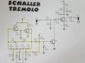
So after trying a design for my Tremolo using a 555 timer and opto isolator using an LED and failing to get rid of a clicking sound at the output,
I bread boarded another design using an op amp instead of the 555 and guess what?.....STILL had the clicking sound so it wasn't the fault of
the 555 crowbarring the supply rail, I removed the LED from the circuit and it made no difference so I have given up with the
opto versions and have just built this circuit and so a new problem OF COURSE!!!!
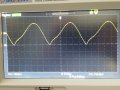
the top of the waveform is a beautiful sweeping curve, the bottom however is very different, it seems to dive into the ground
then sharply bounce back up......where do I go first to remedy this please?
Only the circuit in yellow has been built so far.
Neil.
I bread boarded another design using an op amp instead of the 555 and guess what?.....STILL had the clicking sound so it wasn't the fault of
the 555 crowbarring the supply rail, I removed the LED from the circuit and it made no difference so I have given up with the
opto versions and have just built this circuit and so a new problem OF COURSE!!!!
the top of the waveform is a beautiful sweeping curve, the bottom however is very different, it seems to dive into the ground
then sharply bounce back up......where do I go first to remedy this please?
Only the circuit in yellow has been built so far.
Neil.
Attachments
-
 322 KB Views: 37
 -
 677.8 KB Views: 30


