 Facebook
 Google
 GitHub
 Linkedin
I have included the circuit that is giving me problems and could use some advice please, well sort of, I am using the single stage amp section which is working very nicely, I have up on the phase shift part after I realized I can't alter the frequency easily and replaced it with an astable NE555 timer circuit (not shown)....my problem is that on the base of Q1 I see the signal out from the NE555, I have nothing on the Collector except 9v.....the output from the amp section, the output from Q2 is the oscillator, not my audio signal....its like I am amplifying the output from the NE555 instead of my audio input?
Neil.
Neil.
Attachments
-
2.3 MB Views: 11
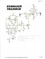

") ). The Schaller oscillator output is approximately sinusoidal, swinging between 0V and 8V, whereas the 555 output is a square wave. You might need to 'round off' the square wave before using it to modulate the audio.
). The Schaller oscillator output is approximately sinusoidal, swinging between 0V and 8V, whereas the 555 output is a square wave. You might need to 'round off' the square wave before using it to modulate the audio..PNG")


