New transformer for millivoltmeter

Thread Starter

Treeman

Joined May 22, 2014
157
Hi,
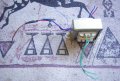
I've just been given a 110v millivolt meter . A MadellCA2171. In UK I need 240v units so I wondered if just changing the transformer is all I need to do?
On the main board is an L7815 regulator. There is nothing written on the transformer.

I'm guessing but would a 240/16v transformer be the ticket?
The current transformer has 2 wires out to the board.

Do I need au uprated fuse?
Thanks.
 

MrChips

Joined Oct 2, 2009
30,821
Is the transformer internal on the unit?
Or is it an external power adapter?

Yes, you can change the transformer. Or you can get a 240/120 step down transformer which might come in handy for similar situations.
 

Thread Starter

Treeman

Joined May 22, 2014
157
Ok I have removed the internal unit and this is what I have (see pic).
2 questions.
1. Can I use this transformer. The Brown live lead is joined to the Blue and red indicating to me at least this is a 240/110 transformer divided up to get 110v.
(2nd blue red pair go to fuse) and the two green to board.

2. Do I need to examine anything on the circuit board to get me the correct voltage output (lm7815 reg on board)? Or is anything close to 15v OK to use.

Thanks.
 

Attachments

MrChips

Joined Oct 2, 2009
30,821
Good chance you are correct.
Before you disconnect the red and blue wires, label the wires:

#1 - RED connected to BROWN
#2 - RED alone
#3 - BLUE connected to BROWN
#4 - BLUE alone

For testing only:
Separate the RED and BLUE from the BROWN wire.
Connect #1 RED to AC LIVE.
Connect #2 RED to #3 BLUE.
Connect #4 BLUE to AC NEUTRAL.

You need to get the phase correct.
Test the transformer disconnected from the unit to verify your voltages.

BTW, the mains wiring might be wired incorrectly.

This is the correct way to connect AC mains circuit:
The mains LIVE (AC mains brown) MUST be connected to the fuse.
From the fuse to the POWER ON/OFF switch.
From the switch to the transformer.
From the transformer to the NEUTRAL (AC mains blue).
 

Thread Starter

Treeman

Joined May 22, 2014
157
Good chance you are correct.
Before you disconnect the red and blue wires, label the wires:

#1 - RED connected to BROWN
#2 - RED alone
#3 - BLUE connected to BROWN
#4 - BLUE alone

For testing only:
Separate the RED and BLUE from the BROWN wire.
Connect #1 RED to AC LIVE.
Connect #2 RED to #3 BLUE.
Connect #4 BLUE to AC NEUTRAL.

You need to get the phase correct.
Test the transformer disconnected from the unit to verify your voltages.

BTW, the mains wiring might be wired incorrectly.

This is the correct way to connect AC mains circuit:
The mains LIVE (AC mains brown) MUST be connected to the fuse.
From the fuse to the POWER ON/OFF switch.
From the switch to the transformer.
From the transformer to the NEUTRAL (AC mains blue).

I was wondering about the 'correctly' above - looking at other items around the house they are wired 'incorrectly' (1970's amp, this millivolt meter). Is this a change of wiring regulation or just the safest method?
 

MrChips

Joined Oct 2, 2009
30,821
I have seen factory built instruments wired with the fuse on one leg of the transformer and the power switch on the other leg.

Consider the consequences:

Case #1
If the fuse is on the LIVE AC MAINS, then when the power switch is OFF the transformer is still LIVE.

Case #2
If the power switch is on the LIVE AC MAINS, then if the fuse blows the transformer is still LIVE if the switch is on.

The correct method is the fuse MUST be the first component that is connected to LIVE AC MAINS. The next component would be the power switch. If either fuse or switch is open LIVE AC MAINS is cutoff from the rest of the circuit.
 

Thread Starter

Treeman

Joined May 22, 2014
157
_IGP7734.JPG Don't worry Mr Chips - I have been thinking of the consequences unlike the Manufacturer! Att. are the completed Pics. It took me ages but was a good experience so thanks for the help; if I hadn't asked then I would have just put it back as before and made it even more dangerous.
Always good to ask.

There is no resistance between Earth Pin and chassis. Tick.
Any other checks for safety?
Output to board is 20vac. Sound right?

_IGP7734.JPG
 

Attachments

MrChips

Joined Oct 2, 2009
30,821
There is no resistance between Earth Pin and chassis. Tick.
Wrong.

The GROUND tab from the AC MAINS connector must be connected to a ground lug fastened to the chassis. You can put the ground lug on one of the bolts used to secure the transformer.
 

Thread Starter

Treeman

Joined May 22, 2014
157
Wrong.

The GROUND tab from the AC MAINS connector must be connected to a ground lug fastened to the chassis. You can put the ground lug on one of the bolts used to secure the transformer.

That's what I have done in photo 2 Mr Chips. Photo 1 was to show the transformer wiring. It came up as a fullsize pic and wouldn't thumbnail again. Sorry if that confused.

What measurements do I need to take to check safety please?

The unit turns on but the transformer seems a bit stinky (resin?) and warm after a minute or two. Its all unplugged and everyone is still alive. The wife seems unhappy.....
 
Last edited:
Top