PSFB transformer

Thread Starter

mazers

Joined Mar 3, 2026
4
Hello,
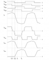
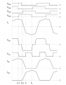
I have been working on a PSFB converterfor a while and I have a really weird problem. Here is my scope view.
1772538789744.png
The yellow line is primary voltage and blue line is primary current of transformer with center tapped. my seconder circiut is diode rectifier instead of SR. The problem is why does my primary current decrease while energy transfer interval ? The transformer goes to demagnetizition in positive polarity. However, the current is supposed to stay constant in freewheeling interval while transformer short-circuit then it needs to go down when primary voltage is negative.
Do you have any idea ?
 

Thread Starter

mazers

Joined Mar 3, 2026
4
it is triggered , thats why it looks like. I am just using current probe and differantial voltage probs to measure primary voltage. Do you have any idea about current form ?
 

ronsimpson

Joined Oct 7, 2019
4,646
Please post the power stages of your circuit. (MOSFETs, transformer, output diodes, filter caps, any resonant inductors)
--------edited----------
I believe this is typical. I can't remember why. What I build has an inductor for storing energy. It also has a transformer for isolation, and stepdown. I think the waveform looks different because of the inductance of the transformer.
 
Last edited:

Thread Starter

mazers

Joined Mar 3, 2026
4
here is my power stage
1772604963443.png
control tecnique and proper waveforms.
1772605000191.png
my worst case transformer inductance is 1mH at full load. at light load , it is supposed to be bigger like 2.5-3mH and I tried 2.1mH and 2.8mH transformers but it is still same. Also , this transformer is step down. I cant understand why the transformer go to demagnetizition while voltage is same polartiy and it is in energy transfer interval , the current cant decrease while transferring energy to seconder. I cant find anything on web and solve in any simulation program.
 

ronsimpson

Joined Oct 7, 2019
4,646
I want to understand your question. Are you questing why the "fast slope" and then the "slow slopes" in the picture?

I want to make a point "AB" that is in the middle of the transformer. We need to show when the voltage is across the Ls and not the transformer.
When you first apply voltage A to B the voltage is not across the transformer, but the supply voltage is across Ls. The current ramps at (supply voltage/Ls). (assume a 1:1 transformer) the current must ramp up to the output current before the supply voltage is applied across the transformer. The "slow slope" is the slope from the output inductor.

Sorry I do not have time right now. I will be back later.
1772638570687.png
 

MisterBill2

Joined Jan 23, 2018
27,160
The magnetic field does not change instantly, so as the primary current is switched off, the magnetic field is still delivering energy. That is how transformers work. The "wiggles" in the secondary current are caused by the oscillations in the primary voltage at the switching points. You haveshown us why that "simulated sine wave" inverter actually works, why it does not destroy everything.
 

ronsimpson

Joined Oct 7, 2019
4,646
It took too long for me to understand the MOSFETS are not driving the circuit, but the output stage is the driving force.
R1=load, C1 is the output cap. L1 inductance is very high for this example.
On your schematic there is no D1, but there is one you just can't see it. Put a meter on the left side of the inductor to ground and the meter will see a diode. It is your two diodes in parallel.
When L1 inductance is very large it becomes a constant current source. If the inductance is 100uH then the current might ramp from 0.8A to 1.2A and back to 0.8A but still acts like a constant current source.
There is 1A in the load all the time. There is 1A in L1 all the time. An inductor wants to keep the current from changing.
From the transformer there are two diodes. I drew them like current sources, I1 and I2.
If you pick up on the left side of L1 you can push current into L1 then to the load. If you let go of the left side of L1 it will fall to -0.7V and pull current out of ground. Any time the left side of L1 is at -0.7V your power transformer has the secondaries shorted out. That reflects to the primary and it is also shorted out, leaving only the leakage inductance.
When the current from I1 or I2 is less than the current in L1 the left side is at -0.7V. As soon as the current is the same the left side picks up off the diode. Now and only now is there much voltage across the transformer.
1772650593003.png
It seems backwards to say L1 can short out the transformer.
It also seems wrong to say L1 stores the energy, not the transformer.
The transformer primary inductance does store a little energy that distorts the primary current waveform. This is not the driving force in the supply.
 
Last edited:

Thread Starter

mazers

Joined Mar 3, 2026
4
Thank you for your interest , you are so helpful .
According to principle of PSFB converter; primary side needs to be short circuit when current circulating in top or bottom side mosfet . Main purpose is using resonance between leakge inductance and Coss of mosfet , achive the ZVS for mosfets. In my circuit , primary current starts to decreace in middle of energy transfer. That is my main problem. If I use larger output inductance , current wants to stay constant and reflects to primary then current wont decrease in energy transfer . Is that correct ? or Is there a problem in my rectifier diodes ? Could they be too slow for this operation ?
And I dont understand what you meant exactly. You modelled D1 as my rectifier diodes ?
1772779509540.png1772779733994.png
 

Attachments

ronsimpson

Joined Oct 7, 2019
4,646
And I dont understand what you meant exactly. You modelled D1 as my rectifier diodes ?
Point C cannot be pulled below ground. It looks like there is a diode D1 that limits the voltage to -1 diode drop.
It cannot be pulled down by DC or AC. I put a diode there for a while but there was no current flow in it.
1772814244309.png
I think the picture in post #1 does not match the picture in posts #5. This has bothered me all the time.

What I built, the Lo has a large amount of inductance. The current is continuous. It never stops flowing. I cannot see. Are you in continuous or discontinuous mode on the output?

What I built was before IC were invented to do what you are doing. I drove the Gate of Q1 & Q4 with the same signals. Q2 & Q3 have the same signal. I never have Q1 & Q3 or Q2 & Q4 on at the same time. I did not need to because there was zero voltage across the transformer during those times. The waveforms look almost the same.

I wish I could stand beside you and look.

I would find a different IC that does this job and read its data sheet. Look for applications notes from a different company. I think the waveforms in your drawings seem to be phase shifted from what I remember.

1772816570929.png
I gave up on the Gate Drive waveforms, I do not understand them.
In this picture the Lo current is continuous.
Ip, at the top and bottom there is a slow slope up then back down. That matches Io current. Good.
Ip, has a fast slope. In my supplies this is when there is no voltage across the transformer. This picture seems wrong to me.
The slow slope is from the output inductor. I think that is clear.

I need to go make some money. Maybe I can come back in 4 hours. I do not have time to finish this picture.
I made a point AB.
Time 1. A=0V B=0V There is no voltage across the transformer.
Time 2. A=0V, B=supply, AB=0V. The supply voltage is across Ls. Because Ls is small the slope is fast. Current what was flowing must slope from +1 to -1 fast before there can be voltage across A to AB. At this time AB to B = 0V.
1772817216063.png
This point is hard to understand. You can drive a voltage A to B but the "transformer" does not see the voltage. It is across Ls.
In your transformer you cannot see AB. In my supply Ls is on the outside. I can see AB.
During the time it takes to charge Ls from plus current to negative current there is no voltage across the secondary of the transformer either.

RonS.
 
Top