New to this board, advice sought for project idea

Thread Starter

cazksboy

Joined Nov 9, 2009
40
Hello all, I just found this message board last week and this is my first post. I've been fascinated with electronics since high school but I've never had any formal education. I would say my soldering skills are good but not great (I need practice!).

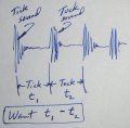
My hobby is repairing antique clocks and I have an idea for a project I want to build but I haven't the foggiest notion how to go about it. My hope is that someone in this community can at least guide me toward the right circuit to build my project. I want to build a diagnostic tool for "setting the beat" of an antique spring-driven or weight-driven clock. "In beat" is when the silences between the "tick" and the "tock" sound are perfectly even, and "out of beat" is when they are uneven. Such a sound is easy for someone with a strong sense of rhythm to hear, but not everyone has such a sense and it's nice to have an instrument to quantify the setting.

I want to build a handheld box containing a small audio amplifier fed by a wire with a tiny microphone or pickup at the end. The mic would be placed next to the escapement mechanism (the source of the tick-tock sound), and the mic's signal would in turn trigger a series of LED's. I'm envisioning a single row of 7 or so LED's, with the center one green for "perfectly in beat" and the ones on the left or right would pulse another color when the beat is close, but not perfect.

I have other design details I'd like to include, but those could be enumerated later. The above is my basic idea. It needs to be inexpensive, above all other considerations. I'm not seeking to patent anything or make a million bucks off this idea because it's already been done by at least two manufacturers - I just want to make a "poor man's version" of this product: http://www.bmumford.com/mset/specs.html . One detail I'd like to build into my box would be a miniature noise gate between the mic and the signal processor so that the mic would be impervious to ambient noise.

Can anyone point me to what kind of circuit would take a signal from a mic and make it drive a series of LED's in the manner described above? Hopefully I've been clear, but maybe I haven't been.

Thank you in advance,
Doug H.
 

Wendy

Joined Mar 24, 2008
23,415
Welcome aboard.

Sounds easy, but I don't have a clue at the moment. You want something to show percentages, or milliseconds? I'm betting percentages myself.
 

Thread Starter

cazksboy

Joined Nov 9, 2009
40
Hi Bill,
Thanks for the speedy reply! Didn't think I'd get feedback so quickly. Hmm, percentages or milliseconds......not sure, really. Here's what I'm thinking...imagine a series of seven LED's in a straight row. Left to right, let's call them #1, #2, #3, etc. on up to #7. Number 4 is the one I want to glow green only when the silences between the "tick" and "tock" sounds are exactly the same. Alright, LED #1 (on the extreme left) should blink rapidly when it's "out of beat" by a defined amount, but as I adjust the clock's beat and get closer to "in beat" (but not perfect yet) then LED #1 stops blinking and LED #2 starts blinking, but a little slower than #1. Similarly, as the clock continues to be adjusted, eventually only the center LED would light up but NOT BLINK. The LED's on the right would blink like #'s 1, 2, & 3 but according to which silence is longer: "tick......tock" or "tock.....tick". I hope I'm making myself clear! I'm not really sure.

Anyway, the gradual visual indication via LED's being triggered by milliseconds or percentages - I'm not sure! Seems like a circuit that could measure every OTHER sound as the "measuring ruler" could be used as the standard by which determining whether the sound in the middle is centered or not.
 

Thread Starter

cazksboy

Joined Nov 9, 2009
40
Ideas, anyone? What kind of circuit would convert a series of pulses from a microphone into a blinking LED depending on how steady the pulses are?
 

Wendy

Joined Mar 24, 2008
23,415
The first thought I have is to somehow start a monostable on a tic and a toc. I'm thinking there would be a silent area, just befor the next sound. The problem is how to convert the duration of each of the 2 pulses into the format you want.
 
It seems like the first problem is to discriminate between the tick and tock of the mechanism. Maybe just a simple counter (flipflop), whose first state starts a shift register (SR) counting pulses. The next (tock) stops the register. The number of pulses counted corresponds to the number of LED's lit. Now you need to hold this data, while a second shift register starts on the (tock) and stops on the next (tick). The second registers data LED's corresponds to the interval between (tock) and (tick).
Now you hold this data just long enough to compare to the first SR. Then the cycle repeats as you adjust your mechanism. When both LED banks are equal, your clock is tuned.

Cheers, DPW
 

Thread Starter

cazksboy

Joined Nov 9, 2009
40
Thanks guys. Those responses make sense to me - now, how do I translate that into a working prototype? I've found a few prototyping designers in the yellow pages but they've quoted me prices approaching nearly a thousand bucks - I'm not savvy enough to actually design & build a circuit like that. Am I stuck with having to pay big dollars for a unit that works?
 

someonesdad

Joined Jul 7, 2009
1,583
If I understand your problem statement right, you want to measure t1 - t2 as shown in the attached figure, right?

If I had to solve this problem, I'd put the microphone next to the clock and connect the microphone's output to an oscilloscope, perhaps through an amplifier. The scope could be used to visually adjust things until t1 - t2 was near zero. This measurement has a discrimination on the order of 1%, more if you use a digital scope that can perform timing measurements.

If this wasn't a good enough measurement, then one could use digital counters to count the time between the ticks and the tocks; effort would be needed to get the triggering right on the different sounds -- this is why a scope approach would be valuable, as you could see how the signals from different clocks differ before you design/build any hardware.

You can get a suitable new scope in the range of $250-$500 (here's one). Since you're probably measuring periods on the order of a second, you'll want a digital storage scope, not an analog scope. Of course, the scope is useful for many other things too (next to a digital multimeter, it's one of the most useful electrical measurement tools to have).

I'd make a trace for you to see what this would look like on a scope, but I don't believe we have any of these old-style clocks around our house.
 

Attachments

Thread Starter

cazksboy

Joined Nov 9, 2009
40
Someonesdad, you nailed it. Your illustration captures what I'd like to be able to measure. The two periods of silence beteween the tick sound and the tock sound need to be equal, so T1 should equal T2, per your illustration. I don't want to resort to an oscilloscope, though, because isn't there a simpler way? I see examples of "rate counters" all the time (sorry, I don't know the right terms), such as on an exercise machine that has a readout of your "steps per minute", or the hospital machine that reads heart rate. For that matter, I have a home heartrate device that reads heart rate that presumably is not as sophisticated as the hospital version. So.....there is such a thing a circuit that takes repetitive events and calculates their rate and outputs a corresponding display.

I guess I'm trying to nail down the following: what simple, inexpensive circuit would emulate that portion of an oscilloscope's function which would compare T1 and T2, and display the discrepancies as a blinking colored LED, and the similitude of T1 and T2 as a steady "other color" LED?

That part comes first for me...I haven't even broached the topics of the refinements I want to include!

Thanks guys for bearing with me...I think we're getting somewhere...
 

Wendy

Joined Mar 24, 2008
23,415
To me, that seems easy. Where I'm having a bit of trouble coming up with something is the discriminator for the two times. I have the sense it should be easy, but I keep thinking you may need to do something with a µC (which I never think of as easy) to compare the two numbers and display them. An analog approach would work fine, as I understand it.
 

Thread Starter

cazksboy

Joined Nov 9, 2009
40
To me, that seems easy. Where I'm having a bit of trouble coming up with something is the discriminator for the two times. I have the sense it should be easy, but I keep thinking you may need to do something with a µC (which I never think of as easy) to compare the two numbers and display them. An analog approach would work fine, as I understand it.
Hi Bill, what is a μC? My electronics knowledge is just what I remember as a hobbyist, with no formal training.
 

beenthere

Joined Apr 20, 2004
15,819
That is short for a microcontroller. There are roughly a zillion on the market. They are, very briefly, microprocessors with built-in memory, external interfacing, and sometimes communication protocols built in. The PIC series from Microchip Technology and the AVR series from Atmel are the most common ones used for hobby projects.
 
Last edited:

Thread Starter

cazksboy

Joined Nov 9, 2009
40
That is short for a microcontroller. There are roughly a zillion on the market. They are, very briefly, microprocessors with built-in memory, external interfacing, and sometimes communication protocols built in. The PIC series from Microchip Technology and the AVR series from Atmel are the most common ones used for hobby projects.
Hi beenthere, thank you very much. I just did a tiny bit of google search for those terms and have found a TON of info. Looks like I've got some reading to do! I appreciate your shedding light.
 

DangerousBill

Joined Jul 21, 2010
30
The graphic attached is the sound picked up by a microphone while an electromagnetic (solenoid) valve is operating. This is basically a plastic coated slug of magnetic material traveling in a tube, but the sound is similar to the ticking of a clock.

The sounds are complex, but they can be essential to the design of the device you're planning. Each pulse starts off with a sudden, high spike, followed by smaller spikes, likely due to bouncing and reflections of sound elsewhere in the instrument. But then there is a period of silence.

If your clocks show similar sound emissions, this might help.

Dangerous Bill
 

Attachments

marshallf3

Joined Jul 26, 2010
2,358
This doesn't sound as difficult as it could be made into, I like the shift registers idea.

Any reason it couldn't just have two rows of LEDs and you adjust it to where the columns are both at the same height?
 
Top