New Thermostat _ How to Power It (3 Wires)

Thread Starter

anav_ds

Joined Sep 18, 2018
11
Okay all my zone valves run on two wires. The "R" wire runs to one side of a transformer and the "W" wire calls for heat. Basically when the thermostat calls for heat, the R and W circuits are closed (joined) and 24volts run through the lines (to the W end) and cause the zone valve to open. Once in the fully open position the red wires at the zone valve circult closes (energizes) telling the associated pump to move liquid. The red wire part of the zone valve is not in play here. I should add I have multi-zones and 3 transformers 120 to 24v 20Va load capacity. I have a spare transformer 40Va capacity.

The problem is I got one of those fancy new thermostats that stated it required a C common wire to power the actual gadgetry of the thermostat.
Lo and behold the brown theromstat casing wire from the wall actually held three wires, one was folded back. Case solved right, wrong!!!!
First I had to find out where that wire ended up in the boiler room. Did that found it, connected to one of the transformers and to the correct C pin on the thermostat.
Great right! Wrong.......... Nothing happened.

Apparently I need a fourth friggen wire to complete the 24v circuit to power the thermometer (similar to how the R and W circuit works I guess)?
I am thinking there must be a way to connect the common wire up in the boiler room such that it gets 24volts full time.................

Would it be feasible to connect the C wire in the boiler room to the yellow return wire from the Valve Motor that is heading to the other side of the transformer (opposite the R wire load side). I tried connecting them both to the transformer but I am thinking they should connect first then to the transformer?

Any ideas welcome............
 

LesJones

Joined Jan 8, 2017
4,544
You need to provide miore information. Post the documentation for the new thermostat. If the new thermostat does reqire power (Rather tnan just being a set of contacts operated by a bimetal strip etc.) Then we don't know if 24 volts AC is the correct power source for the thermostat electronics.. You can get modern digital thermostats that are battery powered.. I have one that runs for a few years on two AA cells.

Les.
 

Thread Starter

anav_ds

Joined Sep 18, 2018
11
You need to provide miore information. Post the documentation for the new thermostat. If the new thermostat does reqire power (Rather tnan just being a set of contacts operated by a bimetal strip etc.) Then we don't know if 24 volts AC is the correct power source for the thermostat electronics.. You can get modern digital thermostats that are battery powered.. I have one that runs for a few years on two AA cells.

Les.
Hi Les, Its the Honeywell Lyric T5. No batteries required. I called them and they said I need a fourth wire. They said I need to create a similar circuit to the R-W circuit. Use a C wire to connect to the C pin on the thermostat and an Rc wire to hook up as well as the regular R wire. The idea here is that the Rc wire and C wire will be a closed circuit running all the time to power the thermostat alone. It has no batteries. I don't have a fourth wire.........
 

tomtmook

Joined Aug 10, 2008
5
Now you need to find out if the control box on the boiler has the connection for a C wire. Can you get the make and model of the control box? Look that up and see if it has a C terminal to connect your third wire.
 

Thread Starter

anav_ds

Joined Sep 18, 2018
11
Now you need to find out if the control box on the boiler has the connection for a C wire. Can you get the make and model of the control box? Look that up and see if it has a C terminal to connect your third wire.
Haha, pay attention there are no control boxes, I have zone valves and electrical boxes where multiple wire connections are made to connect the thermostats and zone valves and transformers.

I think the answer is to ensure the C wire is properly hooked up to the right transformer with the yellow return wire from the valve motor.
 

LesJones

Joined Jan 8, 2017
4,544
I found this link while looking for information on your thermostat. The picture labelled "Step down transformer" seems to be the way that I would expect it to work with three wires. The side of the transformer 24 volts secondary that is connected directly to one side of the zone valve should be connected to the "C" terminal on the thermostat. The other end of the 24 volt winding should go to the 24 V AC power terminal on the thermostat. The wire from the zone valve should go to the Heat terminal on the thermostat. Make sure that you have not swapped over the 24 volts from the transformer and the wire from the zone valve. At the thermosat measure the voltage between common ant the 24 V AC terminal. You should get a permanent 24 volt AC reading. (If the wires are swapped over The permanent 24 volts will be on the heat terminal.)

Les.
 

Thread Starter

anav_ds

Joined Sep 18, 2018
11
I found this link while looking for information on your thermostat. The picture labelled "Step down transformer" seems to be the way that I would expect it to work with three wires. The side of the transformer 24 volts secondary that is connected directly to one side of the zone valve should be connected to the "C" terminal on the thermostat. The other end of the 24 volt winding should go to the 24 V AC power terminal on the thermostat. The wire from the zone valve should go to the Heat terminal on the thermostat. Make sure that you have not swapped over the 24 volts from the transformer and the wire from the zone valve. At the thermosat measure the voltage between common ant the 24 V AC terminal. You should get a permanent 24 volt AC reading. (If the wires are swapped over The permanent 24 volts will be on the heat terminal.)

Les.
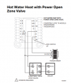
Hi Les, yes that seems to be the common (pun intended advice). I found this on the sister model T6........... It basically echoes your advice. So I should ensure that
A. I am using the same transformer for the circuit.
B. Ensure the Yellow return wire from the zone valve goes to the opposite side of the transformer as to where the R wire from the thermostat goes.
C. Ensure the common wire from the thermostat goes to the same side as the yellow wire return
D. It is not necessary to join the yellow return wire and the C wire before going to the transformer lead (I can connect both wires right to the transformer lead.)
zonevalvet6.PNG
 

wayneh

Joined Sep 9, 2010
18,181
FWIW, my Ecobee 3 smart thermostat came with a little device you install in your furnace room. Ecobee calls it a PEK, a Power Extender Kit. It connects to the 5-wire terminals at the furnace control board and sends power over a 4-wire system. Perhaps your smart thermostat could be adapted using a similar device.
 

Thread Starter

anav_ds

Joined Sep 18, 2018
11
I found this link while looking for information on your thermostat. The picture labelled "Step down transformer" seems to be the way that I would expect it to work with three wires. The side of the transformer 24 volts secondary that is connected directly to one side of the zone valve should be connected to the "C" terminal on the thermostat. The other end of the 24 volt winding should go to the 24 V AC power terminal on the thermostat. The wire from the zone valve should go to the Heat terminal on the thermostat. Make sure that you have not swapped over the 24 volts from the transformer and the wire from the zone valve. At the thermosat measure the voltage between common ant the 24 V AC terminal. You should get a permanent 24 volt AC reading. (If the wires are swapped over The permanent 24 volts will be on the heat terminal.)

Les.
HI Les,
Another think I have noted is that the wiriings from thermostats and zone valves do not necessarily end up at the same transformer.
Meaning, yes all the R wires from the thermostats go the the load side of the transformer and all the return wires from the zone valves go to the opposite side of the transformers........ BUT its not necessarily the same transformer.
Put another way, an R wire from a thermostat could be on the load side of transformer #1, but the yellow return wire for that associated zone valve ends up on the non-load side of transformer #2.

I am assuming this is not an issue as a close circuit with 24v is as good as any other.
The question I have, is, what about my common wire? Should I simply ensure that its on then same non-load side as the yellow return wire from the zone valve, or on the non-load side of associated with the transformer of the R wire??

(not likely to purchase an ecobee just to get the adapter LOL, but will look at black friday sales perhaps for a new unit altogether, and could be an ecobee).
 

wayneh

Joined Sep 9, 2010
18,181
(not likely to purchase an ecobee just to get the adapter LOL, but will look at black friday sales perhaps for a new unit altogether, and could be an ecobee).
Yeah, I wasn't suggesting a different smart thermostat (although the Ecobee is a nice one). I was just wondering whether your thermostat might be able to do something similar, perhaps with an accessory from the manufacturer. Have you asked them for advice? It's a very common issue.
 

LesJones

Joined Jan 8, 2017
4,544
If the 24 volt secondaries are floating then the common return must be to the same transformer. As the system worked with the old thermostat it is possible that the common side of all the transformers was connected together. Have you checked that you have a permanant 24 volts AC at the thermostat ?

Les.
 

Thread Starter

anav_ds

Joined Sep 18, 2018
11
If the 24 volt secondaries are floating then the common return must be to the same transformer. As the system worked with the old thermostat it is possible that the common side of all the transformers was connected together. Have you checked that you have a permanant 24 volts AC at the thermostat ?

Les.
Hi there, No, there is not.
At the transformers I get 10-10 15-15 and 15-15 (one lead then the other)
At the thermostat each wire is like 1v or less.
Nothing is 24 volts and the RW do not form a closed circuit until there is a call for heat and the thermostat connects the R and W wires.
 

LesJones

Joined Jan 8, 2017
4,544
The way you have written down the voltage reading make me think you are measuring with respect to something other than the other end of the transformer. You should have one meter probe on each end of the transformer. If you are measuring using some other reference point then what is it ? Without the thermostat connected I would expect your meter to read 24 volts AC between the red and the white wires at the thermostat connection point. (This will be the 24 volts from the transformer via the motor winding in the zone valve.) Are you shure you have identified the extra wire from the thermostat connection point at the boiler end ?

Les.
 

Thread Starter

anav_ds

Joined Sep 18, 2018
11
The way you have written down the voltage reading make me think you are measuring with respect to something other than the other end of the transformer. You should have one meter probe on each end of the transformer. If you are measuring using some other reference point then what is it ? Without the thermostat connected I would expect your meter to read 24 volts AC between the red and the white wires at the thermostat connection point. (This will be the 24 volts from the transformer via the motor winding in the zone valve.) Are you shure you have identified the extra wire from the thermostat connection point at the boiler end ?

Les.
Hi Les, that is correct, only one lead at a time the other end to the metal jacket casing one often sees around wiriing.
I would expect 24v if connecting the two ends of the transformer, I can verify but fully expect that to be the case.
 

LesJones

Joined Jan 8, 2017
4,544
Voltage readings from a floating power supply with respect to earth. (Which is what the metal casing is connected to.) are meaningless. You are only getting reading due to the reactance of stray capacitance between the secondary winding on the transformer and earth. ( Your meter will have a very high input impedance.) If earthed metalwork is available at both the thermostat end and the boiler end of the extra wire you have found then you can use it to check if you have the right wire ends. With your meter set to a lowish ohms range (Say 200 ohms.) and both ends of the wire disconnected from anything else you should get a very high reading between the end of the wire and earth. On the 200 ohm range will give an over range display such as OL ) If you then connect the far end of the wire you are tracing to earth the meater reading should go down to a few ohms or less. I suggest that you start by confirming that you have identified the correct wire at the boiler end the boiler from the thermostat end. I suggest you turn off the power to the heating system to do the resistance tests.

Les.
 
let me add my $0.02.

"C" can be "mysterious" because it wasn;t even labeled on old stuff.

Flame proving signals (flame rectification) depend on the "phase" of the 24 V secondary.

Flame rectification does ground one side of the secondary and it matters what side.

"C" is just the "non-R" side of the transformer.

I'd start with one zone valve and then branch out from there. Any other secondary should be isolated.

The new fangled thermostats have Rc and Rh, so you can have a transformer for heating and a transformer for cooling. If you have a single transformer for heating and cooling then Rc is jumpered to Rh and call it R.

yes, on a call for heat, 24 VAC will exist from C and W.

Another way to troubleshoot (doesn't work all of time) is measure the voltage across the R and W contact. On a call for heat, the value across the "relay contact" will be zero and 24 VAC if not calling for heat providing the solenoid valve is wired.

Hopefully, that info will help you.

There needs to be 24 VAC BETWEEN R&C at the thermostat, No pint continuing if there isn't.
 

Thread Starter

anav_ds

Joined Sep 18, 2018
11
Good day. I solved my issues and thanks to all contributions. Read on if you have three wire thermostat bundling. In my case multizone hotwater heating with 8 zone valves, 3 transformers and a propane boiler (and 5 pumps). This applies to those moving from a two wire honeywell thermostat (which covers the older mercury tube type, OR the LCD display type that needed batteries to display and programme). All my wiring bundles included a third wire folded back, which we will use for the Common Wire discussed. (no fan, no cooling, no heat pump, just heat.

A. The steps are as follows.
a. identify which wire is going to the load side of the transformer in the boiler room (should be the wire currently hooked into your R connector). Confirm proper wiring.
b. identify which wire is going to the associated zone valve for that zone (should be the wire currently hooked into your W connector). Confirm proper wiring
c. locate which transformer (if only one this is dead easy) the R wire is connected too, and its usually connected to the side that says load.
d. locate the end of the common wire for that thermostat in the boiler room. e. attach the commonwire, typically with a marette and a new piece of wire, to the SAME TRANSFORMER as the R wire BUT to the opposite side(screw).

Synopsis A: With a multi-transformer scenario, I found the easiest thing to do was find the yellow wires (coming from my honeywell zone valves and attached to the motor) and found which one was connected to the W wire from the wire bundle - this was a one to one connection. (The other yellow wire was joined with other zone valve yellow wires and was connected to a wire going to one of my transformers on the opposite side to the load side on that transformer and thus not helpful.). Finding the W wire allowed me to trace back to the 3 wire bundle from that thermostat coming into a common wiring box. Now I could locate the Common wire and importantly the R wire. I had to know which transformer the R wire went to, in order to ensure the common wire went to the opposite side of the same transformer.

B. AT thermostat the following step applied.
(a) Ensure the R and RC switch is down, in the 2 slot position (both holes exposed)
(b) Connect the C wire to the C post/slot
(c) Connect the R wire to the R post/slot
(d) Connect the W wire to the W post/slot
(e) create a little jumper wire (u shaped with exposed copper at the ends) and CONNECT R to Rc

Explanation: The R and W wires form a 24 volt circuit WHEN the thermostat calls for heat, (the thermostat joins the R and W wires creating a circuit for juice to flow). The jumper between R and Rc creates and additional circuit between Rc and C WHICH HONEYWELL OMITS in all their literature. Tech support kept telling me I needed four wires, R,W,C and Rc and that I needed to create a similar circuit to RW, using C and Rc. Well by using the jumper I effectively used the Juice on the R side sharing it with Rc. Since the honeywell internally connects Rc and C, the needed circuit is established from the get go and the thermostat powers up. When the thermostat calls for heat, the R and W are connected and the zone valve motor turns on and operns the valve (tested and works).

So the two keys are (1) knowing that honeywell uses the Rc slot and C slot for power to the unit and (2) the C wire has to be on the same transformer but opposite side in the boiler room If you have the different standard square sized honeywell thermostat or find the video on you tube for WIFI honeywell, you will see that they have the jumper already in place!!! Good luck with your own situation. :)
 
I think you have something mixed up.

Rc is R(cooling)
R is equal to Rh or R(heating)
C is common

Two wire thermostat for heating only has R and W. The C connection is at the furnace.
It could Have G if Fan is used.

With heating, usually the "furnace controls the fan" with an overide. he fan is either temperature or timed.

In cooling, usually, the "thermostat controls the fan"., again with G being an overide.

Since you don;t have cooling, you don't need Rc. You do need something to power the thermostat, though, that is LIKELY C and Rh or C and R.

Since the honeywell internally connects Rc and C, the needed circuit is established from the get go and the thermostat powers up
This would cause a direct short. Your (a) and (c) basically confirm this.

R, Rc and/or Rh is the load side which will be switched.
C is the common side of the transformer.
 
Last edited:

Thread Starter

anav_ds

Joined Sep 18, 2018
11
No, nice try but wrongo!
There is no fan associated with my propane boiler which is controlled by zone valves and pumps for infloor radiant heat mostly and some hotwater baseboard.

Correct I am using Rc and C to power the thermostat. However I am powering Rc by jumping R to Rc. :)
In the Honeywell, the thermostat connects Rc to C for this very purpose (call them!!).
Or look at the honeywell wifi thermostat (diff model) which comes with R and Rc already jumpered.
I just had to ensure the C wire was attached to the same transformer as the R wire (opposite side).
Most of my zone valves and thermostats are not necessarily using the same transformer but they do subscribe to being on the correct side of the applicable transformer (R wires to load side, returns from zone valve to non-load side).
 
Top