 Facebook
 Google
 GitHub
 Linkedin
Hello. I'm really new to all this, in trade school for hvac. Electrical fundamentals right now. What if you have more than two numbers? (I haven't learned anything NOT the hard way in a long time, and just getting back into learning, and any level of math)
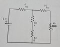
I finally solved this, but with your formula, how would this be solved
I finally solved this, but with your formula, how would this be solved
Attachments
-
 164.5 KB Views: 32


") It might be good practice for more complicated problems though.
It might be good practice for more complicated problems though.


