New dumb question(got a million of them)

ronv

Joined Nov 12, 2008
3,770
Don't know why my logic diagram shows as a broken link now, will try again.

What would really be great would be a second comparator on the cap bank that would take the place of the "discharge/arc on timer". That would start the "charge/ arc off" timer when it went below a set low voltage, but an arc on timer will be fine.

View attachment 84131
I started on the logic, but it got complicated pretty fast so I want to rethink it.

A couple more questions so we don't have to do it over.

I think you want to switch in a couple more caps. Maybe 2 more so you would have 1 for say 20 usec. plus one for 50 usec. and plus one more for 100 usec.????

Do you have a link for the stepper motor controller so I will know how long a pulse, what voltage, etc. that it wants???

Do you have a link to the specs on the stepper controller so we know how long a pulse and what voltage etc. that it wants???

Do you have a link to the specs on the stepper controller????

You would like the on time adjustable???
 

Thread Starter

shortbus

Joined Sep 30, 2009
10,049
Ron, the discharge caps will be in steps, 5uF, 5uF, 5uF, 10uF, 10uF, 15uf. The first 5uF is not switchable the other ones can be switched into the circuit in any needed configuration as needed to suit the burn/cut conditions.

Both the arc on time and the arc off/recharge time should be adjustable. If there could be a low voltage comparator in the cap bank circuit (not the gap circuit), the on time would be self adjusting. It would turn off the arc on time when the cap bank voltage goes below a set level, starting the next step of the sequence, the off time. This would be in addition to the gap voltage window comparator.

I'll look for the manual for the stepper driver. It's on another computer. Found them on line, have two different brands available but the controls are very similar.
 

Attachments

Thread Starter

shortbus

Joined Sep 30, 2009
10,049
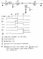
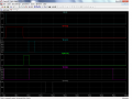
@ ronv, OK, here is a logic timing diagram. Know I don't draw them correctly, been told before. But since this is an asynchronous logic, thought this would suffice. Got an idea for the actual logic but can't figure how to connect all the steps into one schematic. So will draw them out one section at a time and label what they control. There are a few steps that are the same just different sections controlled.

edm 082.jpg
 

Thread Starter

shortbus

Joined Sep 30, 2009
10,049

Attachments

ronv

Joined Nov 12, 2008
3,770
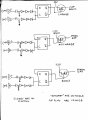
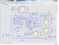
OK, think maybe this will work. As in my other thread on logic pins http://forum.allaboutcircuits.com/t...-another-of-my-million-dumb-questions.110247/ I don't show a lot of the other needed parts to make this a viable circuit, for now those are all implied, this is the very basics of a real circuit. A proof of concept I guess it could be called. @ronv please have a look.
Have a look at this. You may need to print it out to see the test points. The name of the point is above the waveform, so what we have is the circuit and the timing it generates. The waveforms are for a normal arc. I will post some move in and move out and no arc wave forms later, but this should get you started looking. I need to clean it up and simplify it a bit, then I'll post the spice file for everyone to play with. See what you think. Back in a while.
 

Attachments

Thread Starter

shortbus

Joined Sep 30, 2009
10,049
Ron, not real sure what the graph is showing. What is V(swin)? Way more complicated than my logic circuit.:) Did you have a look at mine? I see you use a different edge trigger subcircuit. Like yours better, mine came from a website that I thought was pretty good.
 

ronv

Joined Nov 12, 2008
3,770
Ron, not real sure what the graph is showing. What is V(swin)? Way more complicated than my logic circuit.:) Did you have a look at mine? I see you use a different edge trigger subcircuit. Like yours better, mine came from a website that I thought was pretty good.
V(swin) is the signal that samples the window. You want to sample it somewhere in the middle of the discharge so you need to wait a while before you look at the window.
Yes it is a lot more complicated. Let me try to describe all the combinations.
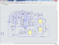
Here is a new schematic. The first had a couple of bugs and I think this one is easier.
V3 and V1 are a reset/start (or run) switch. It needs to start in the reset position to reset the counter U1, and the flip flops U15 and 16 to a known state (off).
The heart of the circuit is the counter U1. We will use it as multiple flip flops to create mostly sequential logic.
So reset sets the counter to zero.
Once the switch is put in the start position and reset is on the counter is "clocked" to one by U4 thru U2 and Charge is sent to the charge circuit from earlier.
Once charge is set and charge ok is returned from the other circuit the counter is again advanced thru U31 and U2 to discharge. This turns on discharge 130 to the other circuit to turn on the high voltage to the spark gap. It also triggers the 2 timers U12 and U10. U12 timer is set to about 120 usec. - longer than the maximum discharge time. If no arc is detected before it times out the in latch U16 will be set and an 'IN" sent to the motor controller. (CIN) This fires the timer U24 that delays the next cycle to give the motor time to move. U10 is used to keep the next cycle from starting for 400 Usec so we don't draw more current from your transformer than it is rated for.If discharge is active and an arc is detected the counter is advanced to arc thru U8 and U2. This triggers the discharge timer U25 that is used to adjust the discharge time you set. It also turns off the 130 volts and turns on the discharge cap in the other circuit. It also delays about 16 usec using R1, C1, U8 and U11 creating swin and stepping the counter to sample (smpl) This allows the flip flops U15 and U16 to "look" at the window. If the window indicates either move in or move out it is sent to the motor controller thru the transistors Q1 or Q2 and again the next cycle is delayed to allow the motor to move. If it is a normal arc Once the counter is at sample and the discharge timer U25 times out the counter is advanced to complete (cmp) thru U34 and U2. This in turn resets the counter after the 400 usec.and we start all over.

It does get pretty complicated in hardware, but I think it will work if it isn't to much to build. A micro would be easier if you were a mico coder.
 

Attachments

Thread Starter

shortbus

Joined Sep 30, 2009
10,049
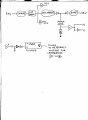
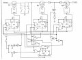
@ronv Finally got something done on this. It uses only one timer, for the off time. It should, at least in my pea brain it does, do the following -

1. Not allow a spark to start without the caps being charged.
2. Set the amount of "on" time by the number/value of caps switched on.
3. Shut the discharge down and start the process over if the caps discharge to an unusable voltage or the electrode shorts out.
4. Only have the "off" time to adjust.

U1, U2, U3 = 4013. U4, U5, U6 = 339. U7 = 4538. Inverters = 40106. And gates = 4081. There are some necessary things left out of the schematic, but they should be implied, and I know they are needed. Such as decoupling caps, pull up resistors on the comparators.

The edge detectors are will pulse for two different times, the one for set, reset of the 4013 and the timer clear will be shorter period of time than the one that blanks the timer start.

The reference voltage will come from the notQ of the timer. When it is low, the rest of the circuit can't function due to the U4 and U5 comparators being shut down. Or at least that's the idea. Didn't put a reference voltage value for U6 cause I didn't know what it will be yet.
edm087.jpg
 

Thread Starter

shortbus

Joined Sep 30, 2009
10,049
Noticed a problem in the above schematic, the connection from the 'clr' pin on the 4538 should go to the same edge detector as the and gate connection.
 

ronv

Joined Nov 12, 2008
3,770
Noticed a problem in the above schematic, the connection from the 'clr' pin on the 4538 should go to the same edge detector as the and gate connection.
Couple of ideas and a couple of questions.
There is no signal going to the bottom of U1, 2 and 3.
I see 92 and 20 volts going to the window comparator. Does that mean you will only move the motor in if it is over 92 volts and out if it is under 20?
You will need some kind of timer or delay to decide when to sample (look) at the window other wise it will send move in at the start of the arc and move out at the end of it every time.
I think you need some kind of timer to decide you haven't had an arc.
I'm not crazy about your pulse generators. They work ok but are more sensitive to noise than the other ones. I can do a picture if you like.
I like your idea of eliminating the on timer. I think we could come up with a way to use one timer for everything if you are willing to have it run a little slower.
I'll look some more.
 

Thread Starter

shortbus

Joined Sep 30, 2009
10,049
Couple of ideas and a couple of questions.
There is no signal going to the bottom of U1, 2 and 3.
I see 92 and 20 volts going to the window comparator. Does that mean you will only move the motor in if it is over 92 volts and out if it is under 20?
You will need some kind of timer or delay to decide when to sample (look) at the window other wise it will send move in at the start of the arc and move out at the end of it every time.
I think you need some kind of timer to decide you haven't had an arc.
I'm not crazy about your pulse generators. They work ok but are more sensitive to noise than the other ones. I can do a picture if you like.
I like your idea of eliminating the on timer. I think we could come up with a way to use one timer for everything if you are willing to have it run a little slower.
I'll look some more.
Oops, didn't catch that one. The signal should come from the positive pulse edge detector,to preset the 4013's in the correct configuration. Will be corrected. Like the one in post #171 was.

The 92V and 20V are just 'place holders', if the circuit is or becomes viable I'll do the math to figure voltage dividers for correct values. Did I mention this stuff is hard for me?:) None of these comparators shown in this schematic are involved with the motor movements. They are strictly for switching the three mosfets controlling charge, discharge and boost or spark ignition.

The comparator, U6, is taking the place of a timer/delay. If the comparator doesn't go to a high output, there is no spark. And the boost/ignition mosfet will continue to stay on until it does.

As always I like seeing your ideas. The pulse generators and the logic involved are all geared toward eliminating what is know as "short pulses" and "missed pulses". Not short as in the electrical sense, but short in the time sense. The whole idea behind the circuit is to make each discharge of the cap bank as close to the same as possible. When using a frequency based timer for controlling the pulse outputs, if the gap conditions don't let the spark ignite at the proscribed time you will get either short length sparking or no sparking. By using the three different comparators U1,2,3, the sparks will/should always be the same length and intensity. This is something no other DIY type edm has been able to do. It really is the basis of what the latest CNC type machine does, just at a smaller/simpler scale. Every other DIY pulse machine uses basically PWM for the pulses, set a frequency then adjust the duty cycle for it to spark.

As always thank you for
 

ronv

Joined Nov 12, 2008
3,770
@shortbus OK. Here is an idea for the easiest one that is still fast:
Two basic parts - a timer, lets say .002 seconds for now. That should be long enough for your discharge caps always to charge to 95 volts so you won't need the cap full comparator and allow enough time for the stepper motor to move if it needs to. We can use the same timer to detect no arc. in other words if we don't see an arc in .002 seconds we will move the motor in and try again.
The second part is a counter like in the first design I made. It is really just a bunch of flip flops like you are using except all in one package.
So at reset the counter will go to zero. With the start switch it will go to one and turn on charge for .002 seconds. At the end of that time it will go to two and turn on discharge. It will also fire the timer again for .002 seconds. If there is no arc in that time it will set " move in" and start over. If there is an arc it will step to three and delay a bit then look at the window comparator to see if it needs to move in or out. If it needs to move out it will turn off discharge (short) and start over. If all is well it will wait for the window to go below 20 volts to turn off discharge and start over.
The other thing you might think about is adding the 113 volt supply is a lot of work for another 18 volts. You could get rid of it.
Let me know what you think, and if I missed something.
 

Thread Starter

shortbus

Joined Sep 30, 2009
10,049
Thanks Ron, I'll have to mull that idea over. I've had this idea in my mind for so long, haven't really considered another way.

About the motor needing to move in, the way I was going to control the stepper drive signals, the only time it would be a problem is at the very start. The drive would blank and hold the last position between pulses.

Any of the machines that don't use a boost/ignition circuit, usually suffer from skipped sparking. The boost circuit was the step that all industrial machine makers adopted after the RC type.
 

ronv

Joined Nov 12, 2008
3,770
Thanks Ron, I'll have to mull that idea over. I've had this idea in my mind for so long, haven't really considered another way.

{quote]About the motor needing to move in, the way I was going to control the stepper drive signals, the only time it would be a problem is at the very start. The drive would blank and hold the last position between pulses.
So if you are drilling a hole what would keep the tool moving towards the part once enough material has been removed for the window voltage to be to high?

Any of the machines that don't use a boost/ignition circuit, usually suffer from skipped sparking. The boost circuit was the step that all industrial machine makers adopted after the RC type.
Just checking.
 

Thread Starter

shortbus

Joined Sep 30, 2009
10,049
So if you are drilling a hole what would keep the tool moving towards the part once enough material has been removed for the window voltage to be to high?
Not sure what your asking here. Once the preset depth is reached a micro switch trips and stops or retracts the ram to the top of travel where another m/s trips and shuts process down.

But if your talking about during the burn, the ram is not supposed to be in constant motion. Those videos I posted are not what is optimal for the process, and one of the big problems of DIY machines I'm trying to eliminate. The gap if seen through a microscope is a rough surface, full of 'hills and valleys' the spark starts and takes down the highest 'hill top' and the jumps to the next one and the next until voltage is not high enough to maintain the spark. The ram really should stay unmoved as the off time and recharge happens. Then since the ram hasn't moved the gap is set corectlly for the next discharge sequence. But if the hill tops are too far from the electrode then the ram will move in. And then stop and allow sparks until the voltage gets too low again and repeat until the set depth is reached.

When talking about the "spark" in this process, it really isn't one single spark per discharge. It actually is thousands of them during each discharge time period. Going from the closes points on both the electrode and work. And as each miniscule high spot is eliminated a new one and new spark is started. When seeing one of these machines in real life burning the many different sparking's are very apparent, but not so much in a video.
 

Thread Starter

shortbus

Joined Sep 30, 2009
10,049
@shortbus OK. Here is an idea for the easiest one that is still fast:
Two basic parts - a timer, lets say .002 seconds for now. That should be long enough for your discharge caps always to charge to 95 volts so you won't need the cap full comparator and allow enough time for the stepper motor to move if it needs to. We can use the same timer to detect no arc. in other words if we don't see an arc in .002 seconds we will move the motor in and try again.
The second part is a counter like in the first design I made. It is really just a bunch of flip flops like you are using except all in one package.
So at reset the counter will go to zero. With the start switch it will go to one and turn on charge for .002 seconds. At the end of that time it will go to two and turn on discharge. It will also fire the timer again for .002 seconds. If there is no arc in that time it will set " move in" and start over. If there is an arc it will step to three and delay a bit then look at the window comparator to see if it needs to move in or out. If it needs to move out it will turn off discharge (short) and start over. If all is well it will wait for the window to go below 20 volts to turn off discharge and start over.
The other thing you might think about is adding the 113 volt supply is a lot of work for another 18 volts. You could get rid of it.
Let me know what you think, and if I missed something.
Not sure I understand how a timer of a few msec and counter with propagation delay of an amount of usec, is faster than a couple of gates and a comparator with a propagation delay of a few hundred nsec? Must be missing something on my end.

Your putting the motor drive and spark generation in the same equation. The motor drive and gap are just a "feed back loop" to the spark generation. Probably not the correct term to use but only one I can think of to explain. The spark generator and motor drive are not really tied together as a system.

The original question of the thread, the comparator and diode drops after the spark gap, is what takes the place of a timer and counter to move the ram forward/in. Until the spark "starts" the motor circuit window comparator will be giving the command to move in. The boost voltage being higher than the open circuit voltage of the discharge will give a 'cushion' distance to the gap, to prevent a short or contact between electrode and work. Once the sparking starts the ram will/should stay in a steady state, until gap gets too large.

The 113V supply is something I already have the components for and really think is needed.
 

Thread Starter

shortbus

Joined Sep 30, 2009
10,049
Got to thinking about an analogy for the ram drive and window comparator interface. Think of it as a heavily dampened volt meter. Moves in when voltage is too high and moves out when it is too low. And stays centered when conditions are correct for sparking. The feedback loop was a poor example. Sorry.
 

ronv

Joined Nov 12, 2008
3,770
="shortbus, post: 860022, member: 61844"]
Not sure I understand how a timer of a few msec and counter with propagation delay of an amount of usec, is faster than a couple of gates and a comparator with a propagation delay of a few hundred nsec? Must be missing something on my end.
I'm not talking about the speed of the logic, but the speed of the machine (arc/second)
There are several reasons for a delay.
One is your transformer is 15 amps. Since it is a full wave bridge driving a large capacitive load it should be derated by .62 or 9.3 amps - see attached.
http://www.hammondmfg.com/pdf/5c007.pdf
So we should keep the average current under that we can do that by making the off time longer than the on time. For example if on and off time were equal and the arc current is 50 amps the power from the transformer would be 25 amps.

Your putting the motor drive and spark generation in the same equation. The motor drive and gap are just a "feed back loop" to the spark generation. Probably not the correct term to use but only one I can think of to explain. The spark generator and motor drive are not really tied together as a system.
Yes a feedback loop is an ok term. But here is the problem as I see it. I could be wrong, I'm no stepper motor expert.
But lets take the example where you are first starting. You know the tool is close, but not how close and you know it is not shorted. I presume you do this with a mechanical gage. But lets say you are 10 or 20 steps away and you have no delay.
If the no arc timer is set to 100 microseconds the motor would try to step in at a 10000 step per second rate. Way to fast me thinks. I think you want to keep the steps per second to a few hundred or a thousand at most. Could be wrong.

The original question of the thread, the comparator and diode drops after the spark gap, is what takes the place of a timer and counter to move the ram forward/in. Until the spark "starts" the motor circuit window comparator will be giving the command to move in. The boost voltage being higher than the open circuit voltage of the discharge will give a 'cushion' distance to the gap, to prevent a short or contact between electrode and work. Once the sparking starts the ram will/should stay in a steady state, until gap gets too large.
I think I understand, but lets say you are arcing along and finally the gap gets to big for an arc. I think you want to give it some time before you decide there is been no arc and not just a delayed arc.

The 113V supply is something I already have the components for and really think is needed.
 
Top