New dumb question(got a million of them)

Thread Starter

shortbus

Joined Sep 30, 2009
10,049
I will need to measure the lead and pitch on my machines head, it's been too long since I messed with it. I say lead and pitch because it is a two start ball screw that is being used.

I agree with a real servo motor being the best set up, but others are doing it with steppers, even most of the small edm 'hole shooters' use to put start holes in parts for wire edm. That said, the old industrial machines used hydraulic cylinders, and there are plans being sold and machines being built(and working) using both RC servo motors (converted to constant rotation) and plain old Maxon style DC gear motors with 80RPM out put.

The stepper motor and ball screw is from an old digital measuring machine that was being scrapped. Some of the drives I have are capable of micro stepping, and all are quarter step capable. The motor is a 200 step per revolution.

Max is correct, I'm using the Langlois book as my heads movement circuit. But I bought over the years many stepper controllers rather than using the discrete component build he used in the book, because they were pretty cheap at the time they were bought and I was going to build a small CNC mill. Since the hobby CNC and 3D printing craze everything like that has gone through the roof price wise.

The OtherRon is here! Whats that make now, 3?:) This is just a 'Z' axis machine, and depth is controlled with a mcro switch and a micrometer head mounted to the ram. So the stepper and it's drive doesn't really care where it's at. And the window comparator will control the gap, since there will be a ~5V window 'null' area to take care of any overshoot.

Ronv, The actual burning process is very slow. I takes several minutes to tens of minutes to move the electrode into the work 0.010" depending on the size of the electrode. The sparks happen fast because as each one creates a 'crater' in the part, a new 'high' spot is also created. And the sparks skip from one high spot in the gap to the next. If you would see a big electrode burning a part, you can actually watch the sparks moving around the area being worked on. I can scan and post the Langlois information if that will help you Ron. And again thank you for your help.
 

ronv

Joined Nov 12, 2008
3,770
I will need to measure the lead and pitch on my machines head, it's been too long since I messed with it. I say lead and pitch because it is a two start ball screw that is being used.

Ronv, The actual burning process is very slow. I takes several minutes to tens of minutes to move the electrode into the work 0.010" depending on the size of the electrode. The sparks happen fast because as each one creates a 'crater' in the part, a new 'high' spot is also created. And the sparks skip from one high spot in the gap to the next. If you would see a big electrode burning a part, you can actually watch the sparks moving around the area being worked on. I can scan and post the Langlois information if that will help you Ron. And again thank you for your help.
Wow, thanks guys! The thread was getting long enough that I wasn't sure anyone was watching it. :cool:
Good news for me, the rate is slow - bad news for you, you have to watch it. :D
So my thinking now is I can either average out 10 milliseconds worth of moves or only send a move every 10 ms or so. We can decide if we want to stop the burns while it moves or just keep going. I guess it would depend on vibrations and stuff. Since it won't happen very often we might as well send a move command and stop for a while - won't make it much slower.

I thought we would save the logic till last so maybe we can go over all the other stuff on the way.

Anybody see anything wrong so far?
 

cmartinez

Joined Jan 17, 2007
8,838
The stepper motor and ball screw is from an old digital measuring machine that was being scrapped. Some of the drives I have are capable of micro stepping, and all are quarter step capable. The motor is a 200 step per revolution.
What brand of stepper and driver are you using?
 

Thread Starter

shortbus

Joined Sep 30, 2009
10,049
Wow, thanks guys! The thread was getting long enough that I wasn't sure anyone was watching it. :cool:
Good news for me, the rate is slow - bad news for you, you have to watch it. :D
So my thinking now is I can either average out 10 milliseconds worth of moves or only send a move every 10 ms or so. We can decide if we want to stop the burns while it moves or just keep going. I guess it would depend on vibrations and stuff. Since it won't happen very often we might as well send a move command and stop for a while - won't make it much slower.

I thought we would save the logic till last so maybe we can go over all the other stuff on the way.

Anybody see anything wrong so far?
Checked the lead screw and it is a 4mm lead, one turn moves the electrode 4mm or 0.157 inch. And with the 200 step per revolution motor it moves 0.000785 inch for each full step.

The usual way is to just apply the window comparator outputs to the direction inputs of the stepper driver, in real time. Then the speed/frequency(adjustable) takes over from that. Window voltage high - motor turn one way, window voltage low - motor turns the other direction. Voltage in the 'window' - stopped. This and the window 'null' gap, keeps the sparks sparking. If the gap signal would be sent only every so often, there is a chance that the gap could widen to the point of it extinguishing the sparking, and the ram not reacting. You set the motor speed so it won't over run the window voltage .

Or the gap could become so contaminated that the unthinkable, at least to one running an edm, happens, the dreaded "DC ARC". This is where the sparking stops and debris in the oil conduct as a high resistance path. Ruins both the part and the electrode, and some times starts the dielectric oil on fire. Not a good thing. And since it doesn't show as a dead short, like the electrode actually touching the work, the machine just keeps on thinking it's doing what it's supposed to do. I've experienced these a couple of times, with an electrode of ~1" square, they light up a room with a yellow glow, kind of like a big low pressure sodium bulb glow.
 

Thread Starter

shortbus

Joined Sep 30, 2009
10,049
What brand of stepper and driver are you using?
The motor on this is a double stack NEMA 23 pac/sci brand. For divers I've got pac/sci, dragon, and somany others that I haven't looked at for so long, don't remember the brands. Used to get them off of Ebay for $3 -$5 plus shipping, had all these ideas for stuff to build. Then learned the electronics was over my head.:(
 

cmartinez

Joined Jan 17, 2007
8,838
The motor on this is a double stack NEMA 23 pac/sci brand. For divers I've got pac/sci, dragon, and somany others that I haven't looked at for so long, don't remember the brands. Used to get them off of Ebay for $3 -$5 plus shipping, had all these ideas for stuff to build. Then learned the electronics was over my head.:(
I'd drive your steppers at 1/2 step (400 steps/rev) if I were you. One thousandth of an inch is good resolution but you might need a bit more than that, since your application calls for extremely slow feedrates.
If you wish to reconsider your driver options, take a look at the geckodrive, they're pretty cool, very powerful and quite affordable (though not in the range of five bucks, of course) They require that you use your own power supply, but I've already designed one for them that's easy to make and with fairly inexpensive components.
 

ronv

Joined Nov 12, 2008
3,770
I'm still lost. :(
I thought the whole gap was only about 0 .001 inch. So I was expecting a step of like 0.0001 inch. Where did I go wrong?
So if I gave it 10 move in commands in 10 milliseconds it would want to make 10 steps?
If so they need to be sent at a rate slower than what it takes for the motor to move. Right?
 

cmartinez

Joined Jan 17, 2007
8,838
I'm still lost. :(
I thought the whole gap was only about 0 .001 inch. So I was expecting a step of like 0.0001 inch. Where did I go wrong?
So if I gave it 10 move in commands in 10 milliseconds it would want to make 10 steps?
If so they need to be sent at a rate slower than what it takes for the motor to move. Right?
Ron, step motors normally have 4 windings that are switched in a special sequence by a driver to generate one step. This switching sequence takes place at a fixed frequency which is independent of speed. But normally speeds of at least 10,000 steps per second can be achieved (depending on the motor, and how much power the driver can deliver). A step motor is capable of pretty high torque at low speeds, but at high speeds they dramatically lose torque, to the point of stalling if the step frequency becomes too high. This is why they're inferior to servos, but cheaper to manufacture and drive. Anyway, I think that a one mil step might bee too rough a distance for this application... I'd suggest attaining a step distance of at least 1/4 of that for smoother control.
 

ronv

Joined Nov 12, 2008
3,770
Ron, step motors normally have 4 windings that are switched in a special sequence by a driver to generate one step. This switching sequence takes place at a fixed frequency which is independent of speed. But normally speeds of at least 10,000 steps per second can be achieved (depending on the motor, and how much power the driver can deliver). A step motor is capable of pretty high torque at low speeds, but at high speeds they dramatically lose torque, to the point of stalling if the step frequency becomes too high. This is why they're inferior to servos, but cheaper to manufacture and drive. Anyway, I think that a one mil step might bee too rough a distance for this application... I'd suggest attaining a step distance of at least 1/4 of that for smoother control.
I agree. Small steps or 1 mistake would run it into the work.
But what about the timing for the steps? The machine will check if it should move in or out on every pulse. These could come at 2 or 3 times every millisecond. I don't think the motor can move that fast, so I'm wondering if I send it say 10 step in commands before it can finish one, what will it do?
 

cmartinez

Joined Jan 17, 2007
8,838
I agree. Small steps or 1 mistake would run it into the work.
But what about the timing for the steps? The machine will check if it should move in or out on every pulse. These could come at 2 or 3 times every millisecond. I don't think the motor can move that fast, so I'm wondering if I send it say 10 step in commands before it can finish one, what will it do?
The previous step must always be completed before the next one can be generated. So yes, you have a point, a timer has to be implemented to guarantee minimum idle time between steps, or otherwise the motor will stall due to extreme acceleration and position will be lost. Unless an encoder is added to the system. Which is something highly recommended when using step motors.
 

ronv

Joined Nov 12, 2008
3,770
Yep, I think maybe a 1 or even .5 mm screw. And maybe I can use 3 or 5 samples and then vote before making a move. Have to sleep on that one.
 

cmartinez

Joined Jan 17, 2007
8,838
On the other hand, you don't have to use a ball screw for this purpose. Ball screws are designed to minimize friction and wear while at the same time able to run at high speeds.
It's perfectly possible to use an off-the-shelf trapezoidal screw as long as you choose the right materials and use a pre-loaded nut. That way you can achieve a much higher resolution per step at a much lower price.
 

MaxHeadRoom

Joined Jul 18, 2013
30,772
The Langlois book recommends a 200 step/rev and around a lead of 40 tpi screw.
Visibly you normally only just see the slight oscillation of the electrode in and out of the work and it emits a constant sizzling sound when burning.
The problem with using water as a flushing agent is it quickly becomes conductive and the dielectric value is too high.
Some have used ethylene glycol mixture with success.
I have used this on the tap disintegrator type machines.
Max.
 

ronv

Joined Nov 12, 2008
3,770
The Langlois book recommends a 200 step/rev and around a lead of 40 tpi screw.
Visibly you normally only just see the slight oscillation of the electrode in and out of the work and it emits a constant sizzling sound when burning.
The problem with using water as a flushing agent is it quickly becomes conductive and the dielectric value is too high.
Some have used ethylene glycol mixture with success.
I have used this on the tap disintegrator type machines.
Max.
Now we're cookin. :)
Can either of you program a small gate array? I'm thinking it's going to be a lot of little wires going with standard logic.
 

Thread Starter

shortbus

Joined Sep 30, 2009
10,049
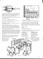
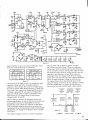
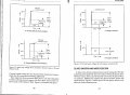
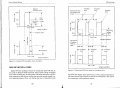
Lol, you guy's are way over thinking the ram movement. It is 'self regulating'. I scanned the schematics from the Langlois book. And a couple of pages from the Jameson edm book showing the wave form of the gap. The second one (called edm 075) shows what I'd like to happen.

Why the step movements don't have to, " use 3 or 5 samples and then vote before making a move." ---edm 072.jpg
The gap voltage (should) spend most of its time in the 'dead zone' no movement of the ram control comparator. This is after the initial spark of the burn, when it first gets close enough to spark. It will only move forward when the spark can't establish. After it is close enough to spark, the next pulse rise time is much faster than the gap control can react, so instead of moving down (it is just a vertical move) the new pulse goes into the dead/working voltage zone again, with no movement needed. The window comparator and stepper drive work together, the comparator giving feed back to the driver and ram. No other logic needed in this part of the circuit.

Until they brought CNC and micros into edm, all of the industrial machines used this type of ram control in some form. Just a comparator giving feed back to a "servo" to control the gap.

Don't have a clue why that file went where it did?? Should have been down with the others, sorry. It is named edm 072
 

Attachments

Last edited:

Thread Starter

shortbus

Joined Sep 30, 2009
10,049
Try to answer the other questions here.

The drivers were acquired many years ago, and were kind of what Gecko is patterned after. They are full industrial drives, just add motor power and direction logic signals, just like a Gecko drive, but for a single axis of movement. I plan on using either 1/2 or 1/4 stepping, all I need to do is flip some 'dip switches' on the drive to change the step rate. The rate will be selected after machine works. In the other thread I was just reporting what the screw and motor were.

Wire edm uses deionized water for the dielectric. It can get away with that because there is much, much less debris from wire edm. It uses a wire of ~0.005" diameter to cut like a bandsaw. Where a sinker edm removes metal from a part completely. Where I worked they bought 4 new Charmilles sinkers and tried using water, after a few months of changing out the deionizer tanks once a week due to clogging they switched to oil like the seller told them. The tanks are like a home water softener tank, 4 per machine, and they had to be sent out to be fixed each time.

Your right about the need for a ball screw, but this one was from a precision machine and was free. It is a preloaded screw with no backlash and way more than is needed but the price was right. Did I mention it was free?
 

MaxHeadRoom

Joined Jul 18, 2013
30,772
The Langlois stepper controller design does not really use the same step direction principle that the common drive does, it incorporates a 'ripple type counter' that is ran from a 555 settable pulse generator.
the direction is detected by sampling the charged capacitor voltage, then counts either up or down, depending on the direction required.
Max.
 
Top