
 Facebook
 Google
 GitHub
 Linkedin

Hi all,
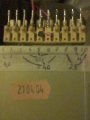
Yesterday hooked it up to find the secondaries. As a surprise came fact, that pin 6 had red dot under it. Made me think, it was the common. Seems, that someone in factory had mixed the pins I guess, since after my results the common is pin 5. Results are somewhat satisfying. Pins 5 to 4 and 5 to 6 have ~22vac.
5 to 3 and 5 to 7 have ~40vac.
I guess this means it's center tapped after all. Seems rather strange, that different voltage secondaries have same tap. (or is it common practice to have it like that?)
These voltages are all I need. But I wouldn't be me if I didn't bother some of you with my questions.
Three last pins are rather strange -
pins 8 to 9 have ~13vac.
Pins 9 to 10 have ~11vac.
Pins 8 to 10 reads total of ~25vac.
(Remeasured 4 times. Human error unlikely but possible)
Thing, that I don't understand is, if pin 9 is CT for that winding, why aren't it in center?
Yesterday hooked it up to find the secondaries. As a surprise came fact, that pin 6 had red dot under it. Made me think, it was the common. Seems, that someone in factory had mixed the pins I guess, since after my results the common is pin 5. Results are somewhat satisfying. Pins 5 to 4 and 5 to 6 have ~22vac.
5 to 3 and 5 to 7 have ~40vac.
I guess this means it's center tapped after all. Seems rather strange, that different voltage secondaries have same tap. (or is it common practice to have it like that?)
These voltages are all I need. But I wouldn't be me if I didn't bother some of you with my questions.
Three last pins are rather strange -
pins 8 to 9 have ~13vac.
Pins 9 to 10 have ~11vac.
Pins 8 to 10 reads total of ~25vac.
(Remeasured 4 times. Human error unlikely but possible)
Thing, that I don't understand is, if pin 9 is CT for that winding, why aren't it in center?
Attachments
-
 34.1 KB Views: 10
Last edited:




