Need your professional help please !!

Thread Starter

Earl Wood

Joined Oct 4, 2015
11
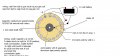
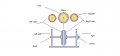
I have built a 16 pole DC magnet motor/generator. I have 16 field coils, 32 neodymium magnets. The stator is fixed containing the coils. Two rotors, one on each side of the stator, are supposed to rotate producing the current. I have a commutator and two carbon brushes mounted side by side. My problem is this: The rotors will not rotate. As soon as I touch a wire to the 12 volt battery, in hopes of rotation of the rotors, they appear to "freeze up". They rock back and forth slightly. As soon as I remove the wire from the battery, I can spin it by hand and it will spin two or three revolutions until it stops on its own, NO power to it. If I spin it by hand first and while spinning I touch the wire to the battery, it "immediately" wants to slow down quickly and stop as if something has a hold on its freedom of movement. One other thing I want to mention, while the wire is on the battery, the rotors stop in the North position of the north coils. If I reverse the positive and negative on the battery, the rotors will stop in the south position of the south coils. I do not know if my brush commutator motor wiring is right. Can you PLEASE HELP ME?. I have been unable to get through this for the past six months. Everything else is done, I need to get over this one. Thank you!!
 

Colin55

Joined Aug 27, 2015
519
Look at a 3-pole motor.
The coils must rotate and the magnets are stationary.
That's what you must do with a 16 pole design.
 

Alec_t

Joined Sep 17, 2013
15,112
How many segments does your commutator have (16?) and how are they aligned angularly with respect to the magnets? Can you post a technical drawing of your setup?
 

Thread Starter

Earl Wood

Joined Oct 4, 2015
11
How many segments does your commutator have (16?) and how are they aligned angularly with respect to the magnets? Can you post a technical drawing of your setup?

Hello Alec, I thank you sir for your help. Just got home, saw your add, and I will send a drawing of it to you. I have 8 segments on the commutator. I feel you are in the right area, just need this wall moved. I will draw one up and have it right to you shortly.

God Bless
Earl!
 

Kermit2

Joined Feb 5, 2010
4,162
It sounds like a severe case of "cogging" to me. With an equal number of magnets and stator coils the magnets want to freeze in a position of min. reluctance. A better scheme is one with different number of magnets to stator poles. 24 magnets, 12 on each side would never let all magnets be in place exactly above a stator at 5he same time and would reduce the grab you are seeing
 

Thread Starter

Earl Wood

Joined Oct 4, 2015
11
Hello Alec, I thank you sir for your help. Just got home, saw your add, and I will send a drawing of it to you. I have 8 segments on the commutator. I feel you are in the right area, just need this wall moved. I will draw one up and have it right to you shortly.

God Bless
Earl!
Hope this helps !!
 

Attachments

Thread Starter

Earl Wood

Joined Oct 4, 2015
11
No Commutation?
Where did you obtain the design?
Max.
Hello Max,

Thanks for your response. This is one I have had for awhile now. I have done some research, and now I want to complete it and can't seem to get rotating. Again, it constantly jerks and or rocks back and forth when DC current is applied to it, NO rotation. If I remove the wire from the battery, I can spin it by hand as it seems to be "free, no holds". As soon as DC hits it, there is a hold on it, NOT froze by any means but somethings holding it back from its running potential.
Thank you!
 

MaxHeadRoom

Joined Jul 18, 2013
30,605
Unless I am missing something, I still do not see commutation?
The result as I see it is very predictable without it, at least for a DC motor?
Max.
 

Thread Starter

Earl Wood

Joined Oct 4, 2015
11
Max, if you're looking at the drawing I posted, I have the commutator marked on it. It is on the yellow colored stator and is the grey commutator . There are eight segments on ht they are are marked.
 

Alec_t

Joined Sep 17, 2013
15,112
All the commutator seems to be doing is switching all the coils simultaneously (since they are all wired in series). How is that supposed to produce rotation? Shouldn't they be switched a group at a time? Shouldn't the number of coils be different from the number of magnet pairs to produce rotation or reduce cogging (e.g. a simple DC motor has 2 stator magnet poles, 3 armature coil poles and a 3-section commutator)?
 
Last edited:

Colin55

Joined Aug 27, 2015
519
I just told you to look at a 3-pole motor and copy the concept. If you are not capable of doing something as simple as this, we are wasting our time with you.
 

Thread Starter

Earl Wood

Joined Oct 4, 2015
11
All the commutator seems to be doing is switching all the coils simultaneously (since they are all wired in series). How is that supposed to produce rotation? Shouldn't they be switched a group at a time? Shouldn't the number of coils be different from the number of magnet pairs to produce rotation or reduce cogging (e.g. a simple DC motor has 2 stator magnet poles, 3 armature coil poles and a 3-section commutator)?
Thanks Alec, I will give this a try to see if we can get over this one!
 

Thread Starter

Earl Wood

Joined Oct 4, 2015
11
It sounds like a severe case of "cogging" to me. With an equal number of magnets and stator coils the magnets want to freeze in a position of min. reluctance. A better scheme is one with different number of magnets to stator poles. 24 magnets, 12 on each side would never let all magnets be in place exactly above a stator at 5he same time and would reduce the grab you are seeing
Kermit, I thank you for your help. I will try this as well to see if I can get rotation.
 

Kermit2

Joined Feb 5, 2010
4,162
http://www.otherpower.com/turbineplans.html

I see from reading this post again, that you have only a single phase wired in the mogen. That will not work the way you want. Your coils MUST be separated into at least two phases and the commutator needs to split the power between those phases and keep them energized opposite of each other.
There is a nice write up of a three phase generator you should read to get a better idea of how to wire them. No info on the page. You have to scroll down screen and click on the links to the various chapters.
 
Top