Hi have a look at this screenshot the k190 kit set and the k190E chip would do the job and you can monitor, data log it to see what's going on and it's cheap
Over the past week or so I have been strangely obsessed with trying to design Differential Controllers - Yes I know, I need to get out more!
Anyway, yesterday I built this one...
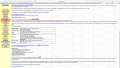
I wanted a Differential Controller that switches on when the collector temperature is about +20°C above the storage temperature but I didn't really want/did not need a variable resistor and the circuit above is what I came up with. By trial and error and a few calculations, the 3k9 resistor (highlighted green) is the value needed to switch on the relay at about +20°C difference. Of course this flutuates very slighly depending on the thermistor temperatures/values.
I tried with different value resistors (3k9, 4k3, 4k7, 5k1) but the 3k9 is the closest that worked. The increase in resistor values increased the difference in temperatures.
The 1M0 resistor (highlighted yellow) is purely the hysteresis resistor causing the hysteresis to be about 0.5°C to 1°C.
I had to decrease the resistor between LM358 output and BC327 base to 1k0 for the relay to switch.
This circuit works very well, the relay switches hard on/off at the exact temperature each time and I am proudly please with it.
Attached is the PCB outline
Any comments/evaluations/observations gratefully received.
You are pushing the output current of the LM358 rather high. As the path for the LED and the transistor base both use a 1k resistor the current in both paths is roughly the same (neglecting the difference in forward voltage between the LED and the transistor base-emitter) you could connect the LED in series with the resistor feeding the transistor base. This uses one less resistor and halves the LM358 output current.
LOL, yes I could, but this may just be a bit OTT!
But, I was thinking of putting a red LED between the output of the LM358 and the ground to indicate when the pump is off. But maybe this plan is an enhancement for the future!
LOL, yes I could, but this may just be a bit OTT!
But, I was thinking of putting a red LED between the output of the LM358 and the ground to indicate when the pump is off. But maybe this plan is an enhancement for the future!
There are bicolor LEDs, or you could just use two, so that one is always on, just the color changes, or also the position if you use two.
One advantage of having an indicator after the relay is that it shows whether power has made it all the way to the load. In other words, a failed relay contact would not light the LED.
One advantage of having an indicator after the relay is that it shows whether power has made it all the way to the load. In other words, a failed relay contact would not light the LED.
I kept thinking about AlbertHall post to me above at post #43. so this morning I replaced the 1k0 resistor back to a 5k1 resistor as in the schematic below (highlighted blue).
For some reason the circuit did not work the first time with the 5k1 resistor but now I think I know why.
Anyway here is the updated schematic....and is working just fine
 Facebook
 Google
 GitHub
 Linkedin
 1.3 MB Views: 4


