Need to find a compatible magnetic speed sensor for speedometer

Thread Starter

MB107

Joined Jul 24, 2016
345
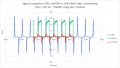
Voltage checks as requested in post 97. Wasn't sure if I had this right so I gave you every combination I could think of.

13.88v actual input voltage measured disconnected
45.7 K Ohm resistor measured disconnected

With 45.7 K Ohm resistor between ground ans speedometer input

0.518V Votlagae across speedometer input and ground
13.37V Voltage across speedometer input and +power
13.88V Voltage across + and -

With 45.7 K Ohm resistor between +13.88V and speedometer input
13.72V Votlagae across speedometer input and ground
106.3mV Voltage across speedometer input and +power
13.89V Voltage across + and -
 

Thread Starter

MB107

Joined Jul 24, 2016
345
Can you sketch the new slot configuration? From your comments in post #96 I think you're hoping to get a Hall sensor output with ~ 50% duty cycle? That won't necessarily result in a ~50% duty cycle being achievable from the adapter output. The problem is that the capacitor will still be needed to get negative pulses from a Hall sensor, and the pulse shape/duty-cycle is governed by cap and resistance values and the speedo input characteristics. Those characteristics are presently unknown, but may be clearer after the post #97 test.
In the end you may need a more sophisticated adapter than the one we've considered up to now, as the present simple one is never going to be able to give a ~constant duty-cycle output over a 10:1 input frequency range, if that's what the speedo is looking for.
Before making new tone wheels I suggest you try the post#95 four-component adapter.
Hello Alec.

While the system appears to work perfectly with simulated signals produced from a 50% cut out wheel, I was wondering if there may be any other sized caps or resistors you could recommend me purchase to optimize the system based on the latest performance information of the previous posts with 50% cutout wheels. I will be purchasing the 10nF caps shortly and would like to get as much as I can on that order to make the shipping somewhat worth while.

This process will be fairly slow. The wheels are now out for bid and the contract will be awarded this Friday to build 5 wheels with 50% cutouts. It will take about 1 month to get the wheels in so in the mean time I will experiment with the circuit in post 95. I'm wondering if there might be an small selection of resistors and caps I should have on hand that may be necessary to optimize any of the concepts that have been investigated for this or the speedometer calibration thread.

Appreciate the help
 

Alec_t

Joined Sep 17, 2013
14,280
any other sized caps or resistors you could recommend me purchase
A 15nF, or 18nF cap perhaps?
We may be at the limit of what the simple circuit can do. Full emulation of a VR sensor would require a considerably more complex circuit, which you seem keen to avoid.
The post #101 measurements are useful and suggest the speedo input impedance is considerably higher than the 47k you had attached. Not surprising if the speedo is expecting a VR sensor signal.
 
Last edited:

Thread Starter

MB107

Joined Jul 24, 2016
345
A 15nF, or 18nF cap perhaps?
We may be at the limit of what the simple circuit can do. Full emulation of a VR sensor would require a considerably more complex circuit, which you seem keen to avoid.
The post #101 measurements are useful and suggest the speedo input impedance is considerably higher than the 47k you had attached. Not surprising if the speedo is expecting a VR sensor signal.
Thank You
I got the 10, 15 and 18nf's coming, along with 3 different size pots and a couple of chips for my other projects.
 

Thread Starter

MB107

Joined Jul 24, 2016
345
I got to try out the new wheels on the lathe today. Lathe only goes up to about 45 MPH so not really enough information yet. But I did find one thing important, and that is that the speedometer works without a zero crossing when the wave duty cycle is 50%. That simplifies things. Now If I determine the speedometer can take being stopped at zero speed without frying something then no extra circuitry will be required. So not ready to do this yet but the last test I will do is just apply 14V to the speedo over night and see if it still works in the morning.

The other thing is the new wheels with integrated threaded holes also work perfectly with the VRS sensors. No stray confusing signals from the hardware.

I'm going to try to make an adapter for my drill press to run these up to 3900 RPM. That will be about 120 MPH.
 

Thread Starter

MB107

Joined Jul 24, 2016
345
I did a little more extensive testing on a modified version of the wheels today. It turns out that the wheel will drive the speedometer flawlessly at least up to 45MPH (as fast as my lathe turns) with either a Hall effect sensor with or without the previously described circuit in place or with a VRS sensor. I was very surprised that it worked well with the VRS sensor. In fact it worked so well, I m now leaning back to the VRS sensor. I don't know why the wheel with the wide slot was so sensitive to the presence of the mounting bolts and this one is not. All testing done today was with mounting bolts present. I'm not out of the woods yet. I have to test this above 100MPH. Plan is to install it in the car. Remove the rear wheels and run it to at last 120MPH.

I believe I have those sensors miss labeled. The green trace is the hall effect sensor without signal conditioning. The red trace is the hall effect sensor with signal conditioning.
 

Attachments

Last edited:

Thread Starter

MB107

Joined Jul 24, 2016
345
So the results are in. Ran the car wheels off to 155 MPH no problems and with one drive around the block, so far a fairly smooth operation. One slight noticeable hesitation in the low speed range. The needle jumped off the bottom 10 MPH peg to 15MPH. All was smooth above 15MPH. Today's testing was performed with the Hall Effect sensor and corrections circuit as previously described. Air gap was set to 0.030" to 0.040". I to see how the low end reacts to a smaller air gap.
 

Thread Starter

MB107

Joined Jul 24, 2016
345
I don't imagine you'll spend much time below 15mph anyway :)
I did a little more testing today. It turns out that the jump I was seeing was actually caused by the car shifting into second just when it reaches the 10MPH point where the needle comes off of the stop. I also got the car up to 120MPH indicated which is really 105MPH due to the gear ration change I have also incorporated.

I am now confident its perfect.

I still would like to try the Hall effect without the signal conditioning circuit as it does appear to work fine on the lathe with the new wheel. I will first have to determine if the speedometer can handle having 14V DC to it at a stop light.

I would also like to try the VRS sensor as it is a total plug and play solution and it seems to be behaving on the lathe.

In any case thanks for all your help. There will be more to follow.
 
Last edited:

MisterBill2

Joined Jan 23, 2018
18,176
The big concern will be with the other two things connected to the sensor, especially the fuel pump relay. The other module may not need to know that the engine is running, but probably it will.There are lots of magnetic pickups availableand probably most of them that can deliver a similar voltage will be OK.
 
Top