I do have a milling machine that will run about twice the speed but no easy way to chuck up the wheel. In any case I ran it on the car and saw absolutely no improvement. But since I had the leads out to hook up the diode I measured the sensor output with the load of the speedometer installed. It appears that with the speedometer installed I loose about 25% of my voltage. That means when I clip the signal at 12 V I will still have peaks at 12V and at 6V. So it appears I need to clip at 6V or less. I don't have problems below 60 mph but I would like to get some margin on this and clip at 3V.
OK I have kind of exhausted all avenues with the Zener Diode it seems to work and do its job but apparently the large fluctuations in amplitude are not effecting the speedometer performance. I believe the problem lies in noise. The attached picture shows the trace with two sources of noise that are occurring at 1/rev on the system. These noise spikes are of high enough amplitude to effect the speedometer.
I recently tried a wave form generator and pumped in a sine wave at increasing amplitude to see ware was the threshold of where the speedometer reacts. It turns out that a 0.4V sine wave will operate the speedometer. And since the sine wave has no significant noise at any amplitude the speedometer runs smooth at all amplitudes above 0.4V and all frequencies.
I have identified frequency of the noise to be at 1/rev of the drive shaft and to exist on two locations on the drive shaft. I believe this noise may becoming from bolts passing in close proximity to the sensor.
Note the last picture is of the tone wheel. It has 4 pulse webs and 3 bolt holes. 1 of the bolt holes is lines up adjacent to one of the pulse webs. The other two bolts are not aligned with any of the webs. This may be a problem.
Anyone care to share thoughts on this.
Also might a hall effect sensor be a better solution here. they actually appear to be cheaper but why didn't Mercedes use one.
The noise pulses are ~0.4V amplitude, so a circuit which responds only to signals above, say, ~0.6V should eliminate the noise problem. Try simply connecting a forward-biased diode (one from the 1N400x series, or even a spare zener diode of any voltage rating) between the sensor output and the speedo input. This might not work, though, since noise amplitude will increase as the revs go up. A circuit with a noise threshold which increased with rpm would be better, but a good bit more complex than you might want.
A Hall sensor would almost certainly avoid the problem. Mercedes may be more comfortable with the older technology, and there would be re-tooling costs to consider if they changed.
I should be able to get away with a threshold of 1.2V since the speedometer doesn't register until 10 MPH. Or higher if I decrease the gap. I will try the zener diode trick since I have spares. So the way I understand it is to put the zener in series like in the picture I posted in post #26. Which side does the diode stripe go to.
I was also able to find a hall effect with the same dimensions that will fit right in place and I have 12V DC power available at the same connector where the speed sensor connects.
Good news:
1) I was able to get another speedometer that I can connect to my lathe and experiment with.
2) I found that if I increase clearance the signal smoothed out at least at high speed. Below 20 MPH is still a challenge but I'm really never there.
Bad news"
1) The hall effect sensor does not work at all, still haven't given up on it. It kind of works backwards from what I need. With the sensor over the gap I get 12V with the sensor over the web the voltage drops to zero. The exact opposite of how the inductive pickup works. That might be fixable with a new wheel with holes instead of slots but making a new wheel is quite a chore. Also the Hall effect will produce a 12 DC voltage directly to the speedo when the car is stopped with the key on.
I haven't tried the circuit in post 46 yet because I cant get the car on the lift for a couple of weeks to try it out. I will try it out on the lathe shortly but I rally am not sure if I need it yet.
A single transistor stage add-on should overcome that.
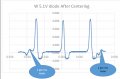
I assume the chart above shows the Hall sensor output? At what mph equivalent?
What was connected to the sensor output when the scope readings were taken?
I figured the signal could be conditioned. And I also figured you would come through for me. Thank you.
I assume that everything in the blue dotted box is what is already inside the hall effect sensor and the three blue junctions you show represent the three leads coming out of my hall effect sensor, where for my sensor top would be power (red), middle would be signal (blue) and bottom would be ground (black).
In any case now that I have a spare speedometer out of the car, measuring "Rmeter" is a little more practical. Previous reading was taken while in the astronaut launch position, probing pins under the dash, while holding a flashlight and reading a meter. I believe the reading I previously reported at 1K was really 1M and that was measured in the incorrect polarity. Evidently there is a diode somewhere in the speedometer circuit. With a speedometer now on the bench resistance is measuring 115K or 1.5M when switching leads and using a digital automotive ohm meter. When using analog meters, one very old automotive meter gives me 5K or infinite. Another analog meter gives me 19K or infinite. My analog meters are very old and the one that reads 19K needs to be tapped to get it to zero or read at all. The digital meter is new and I trust it, but I have seen circumstances where the use of digital meters is frowned upon. Not sure but that may be when reading in the low Ohm range so may not apply here.
That being said how accurately do I need to know the speedometer resistance and is a digital meter OK. The trace I presented in post 48 is of the hall effect sensor output with the speedometer connected to it. If the speedometer is disconnected the trace will be the same except the rounded rise at 12V will be square and sharp just like where the voltage falls off.
My other concern with the hall effect sensor is that with the car at a stop, depending on the drive shaft position the speedometer would be seeing essentially 12V DC for as long as the car was stationary. This may not be a problem but the only way I can test it is to put 14V to a speedometer over night and see if I trash a $500 instrument cluster.
The hall effect sensor trace was taken at ~ 100Hz ~ 60MPH
I have assumed that too. From your scope and meter readings it seems the pullup resistor is internal to the sensor, but if it's not it would be simple to add externally.
In the post #50 circuit the '1k' meter resistance acts with R1 as a potential divider, which is why the output is only ~2.7V. If the meter resistance is actually higher, then that would be better as it would give a higher output (max 12V). The post #51 circuit output will be 12V-ish regardless of the meter resistance.
Your digital meter is fine for resistance checks.
Re the concern over a constant 12V at the meter input, a series capacitor should handle that. Watch this space .
Thank you Alex. Digikey is going to get rich off me $1.00 at a time. I will order parts for all three circuits I will try them all out, that will be about $5.00 . At least I'm approaching the shipping cost.
In the first circuit you list R1 as 3k3. Is that correct, what does 3k3 mean?
Here is what I'm planing on ordering to build all three versions of those circuits. Pleas review, I amm assuming 1 W resistors and for the rest of the stuff I picked the most common in stock parts.
3k3 = 3.3k = 3300. Replacing the decimal point with the 'k' is common practice, because decimal points can easily be overlooked or get lost when schematics are copied.
None of the resistors need actually be rated at more than 1/8W. Common or garden 1/4W will do nicely. The resistance values aren't critical, so even 10% tolerance would be adequate. None of the components will get noticeably warm.
A 100nF cap as I showed will be fine (and very common), instead of the high voltage 200nF you have on your list.
Version 3 of the circuit would be my preferred option. Will you build it on a bit of stripboard? Have you factored in connectors for the circuit?
The striped end of the diode is the cathode and connects to the 12V rail. The purpose of the diode is to clamp the positive-going pulse from the capacitor to the 12V rail so that the base-emitter junction of the PNP transistor doesn't get reverse-biased excessively. R1 helps to keep the PNP switched off when there are no pulses coming from the sensor.
Version 3 of the circuit should do what you want if the speedo resistance is anywhere in the 1k to 1 meg range.
If the speedo is expecting to receive its input from something with a lowish resistance to ground, then you could try a 3k3 or 10k resistor from the speedo input to ground. I doubt that will be necessary though.
Plan is try everything on a bread board. Then final implementation will be to remove the guts from a standard 1" cubed automotive relay and solder the components in its place. The cubed relays are commonly small and light weight enough to be plugged into a universal socket which can be taped to the main wire harness. That will be a challenge for circuit #3.
For circuit #3 I should find a small prototype circuit board that can be mounted into a tiny box. If it gets too big it will all need to be remotely mounted. Any suggestions.
It could all fit on a 0.5" x 0.6" bit of Veroboard (stripboard), like this -
Note the resistors and diode are mounted 'on end' and there is a track cut under R2.
Check the datasheet for the PNP pinout.
Take care that none of the circuit gets shorted to ground, and only the 12V track gets 12V.
If you haven't already got some, I recommend stripboard for knocking together circuits.
Edit: Once it's all working ok, some hot-melt glue to provide extra physical support for the components might be worthwhile.
 Facebook
 Google
 GitHub
 Linkedin


") .
.


