Need Someone To Look Over Schematic Readability

Thread Starter

Evan_g

Joined Apr 29, 2024
18
Hey everyone,

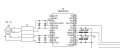
I reached out earlier for some feedback on my first PCB schematic, and I got some really helpful advice. Now I'm hoping those with more experience can take a look at what I've done so far. I'm also wondering if someone could check if my schematic actually works because honestly, I'm not sure! Any feedback or insights would be awesome. Thanks!
 

Attachments

ericgibbs

Joined Jan 29, 2010
21,390
Hi Evan,
It is a good idea to build a hand wired prototype of any project before committing to a PCB.
If you use sockets, where possible, for the proto build, the major components can easily be transferred when ready to the PCB.

E
 

dl324

Joined Mar 30, 2015
18,220
I'm also wondering if someone could check if my schematic actually works because honestly, I'm not sure!
motorDriver.jpg
This schematic is much better than the first one. I think most would prefer to always have ground pointing down. Draw the outputs symmetrically, don't run a wire between the caps and their values. Use component designators (D1, D2, C1, C2, etc). You could use the U or IC prefix instead of Motor_Driver[1234].

You have the capacitors connected wrong. Having 2 in series doesn't make sense. Parallel to ground would.

Can't tell if the circuit will work because a microcontroller controls the motor drivers.
 

Thread Starter

Evan_g

Joined Apr 29, 2024
18
Hi Evan,
It is a good idea to build a hand wired prototype of any project before committing to a PCB.
If you use sockets, where possible, for the proto build, the major components can easily be transferred when ready to the PCB.

E
Yeah I was thinking about purchasing an Arduino but due to budgeting I wasn't able to. I know its a stretch but I'm kind of hoping with help from the community we could make it work, if not so be it, at least I tried.
 

sarahMCML

Joined May 11, 2019
695
View attachment 326133
This schematic is much better than the first one. I think most would prefer to always have ground pointing down. Draw the outputs symmetrically, don't run a wire between the caps and their values. Use component designators (D1, D2, C1, C2, etc). You could use the U or IC prefix instead of Motor_Driver[1234].

You have the capacitors connected wrong. Having 2 in series doesn't make sense. Parallel to ground would.

Can't tell if the circuit will work because a microcontroller controls the motor drivers.
You have diodes back to back straight across the outputs of the two H-bridges, shorting them out. I think what you meant to do was to have a pair on each wire, reverse biased, one to V+ and one to Gnd. It doesn't say anything specifically about back EMF diodes in the datasheet, although it does appear to show the intrinsic ones.
Your power supplies seem to be connected in series with capacitors? Maybe you haven't got to that part yet?
 

Thread Starter

Evan_g

Joined Apr 29, 2024
18
This schematic is much better than the first one. I think most would prefer to always have ground pointing down. Draw the outputs symmetrically, don't run a wire between the caps and their values. Use component designators (D1, D2, C1, C2, etc). You could use the U or IC prefix instead of Motor_Driver[1234].

You have the capacitors connected wrong. Having 2 in series doesn't make sense. Parallel to ground would.

Thank you so much for your help during this project Dennis. I dropped below my updated version of that section with your feedback. I pointed the gnd down, changed the value positions, component designators, used prefixes and attempted to run the capacitors parallel. Could you let me know what you think of my new capacitor connections? Also, you mentioned my outputs weren't symmetrically could you also let me know where and how I should change them? Thanks again for your help!
 

Attachments

dl324

Joined Mar 30, 2015
18,220
Could you let me know what you think of my new capacitor connections?
Better, but now the enable wire is too close to the top capacitors.
Also, you mentioned my outputs weren't symmetrically could you also let me know where and how I should change them?
Draw them symmetrically, something like this:
1720108173844.png vs 1720108286238.png
You can't change the pinout of U1, but you could make a different symbol.

As previously mentioned, the diode connections don't look right.
 

Thread Starter

Evan_g

Joined Apr 29, 2024
18
You have diodes back to back straight across the outputs of the two H-bridges, shorting them out. I think what you meant to do was to have a pair on each wire, reverse biased, one to V+ and one to Gnd. It doesn't say anything specifically about back EMF diodes in the datasheet, although it does appear to show the intrinsic ones.
Your power supplies seem to be connected in series with capacitors? Maybe you haven't got to that part yet?
Thanks for your help Sarah! I'm new to all this electrical engineering so bare with me as I attempt to understand what you noted and let me know if I missed or incorrectly interpreted something. From my understanding you mentioned I incorrectly wired my flyback diodes, which I kind of figured. What your saying about intrinsic diodes is interesting, from my understanding your saying I don't need EMF diodes as theirs already intrinsic diodes in the motor controller?

Focusing on the capacitor wiring issue I attempted to fix that issue through help from another user and posted a screenshot of my updated circuit with said fix. I still don't think I wired that part up exactly right so double checking for me would be nice.

Thanks again for your help!
 

Attachments

Thread Starter

Evan_g

Joined Apr 29, 2024
18
Better, but now the enable wire is too close to the top capacitors.

Draw them symmetrically, something like this:
View attachment 326143 vs View attachment 326145
You can't change the pinout of U1, but you could make a different symbol.

As previously mentioned, the diode connections don't look right.
Yeah I mean that screenshot I sent was kind of a quick fix to see if the idea was right for the parallel capacitors and I'll tidy it up so it looks nicer a little later. I had one last question for that section and it has to due with the ground wire. If you notice at the end where the ground wire and the Vcc wires merge I haven't connected them, its supposed to be like that right?

I figured that's what you mean't by symmetrical outputs but I was double checking to make sure.

For the diode connections I believe what another user mentioned was that its unnecessary as a flyback diode system like the one I was attempting to make is already intrinsically inside the motor controller being used. Although, I may have just misinterpreted her completely so don't take my word for it.
 

dl324

Joined Mar 30, 2015
18,220
For the diode connections I believe what another user mentioned was that its unnecessary as a flyback diode system like the one I was attempting to make is already intrinsically inside the motor controller being used. Although, I may have just misinterpreted her completely so don't take my word for it.
Some motor driver IC's include back EMF diodes and some don't. The advantage of using chips that don't is that you have control over the snubbing circuit. Letting back EMF be larger will let the field collapse faster. That might be important in some cases.
 

Thread Starter

Evan_g

Joined Apr 29, 2024
18
Some motor driver IC's include back EMF diodes and some don't. The advantage of using chips that don't is that you have control over the snubbing circuit. Letting back EMF be larger will let the field collapse faster. That might be important in some cases.
I just made all the changes you recommended throughout my circuit, let me know if you have any more recommendations for me. Also making a quick look through especially my capacitor connections to make sure everything works would be nice.

Thanks for the help!
 

Attachments

MisterBill2

Joined Jan 23, 2018
27,180
The drawings look good except for the very small text in a vertical direction. THAT is simply not readable, and it appears to tie over to another segment with the same text. But not legible again.
As for functioning, I see connections with capacitors in series running to the Vcc terminals. That will not work!! Vcc supply inputs need to be tied to the appropriate power supply positive output. Power filter/bypass connections need the capacitor tied between power + and power -(common, usually)
 

Thread Starter

Evan_g

Joined Apr 29, 2024
18
The drawings look good except for the very small text in a vertical direction. THAT is simply not readable, and it appears to tie over to another segment with the same text. But not legible again.
As for functioning, I see connections with capacitors in series running to the Vcc terminals. That will not work!! Vcc supply inputs need to be tied to the appropriate power supply positive output. Power filter/bypass connections need the capacitor tied between power + and power -(common, usually)
Thanks to some help from the others in the community I was able to make some of those changes earlier but I would be more than happy if you would like to look over my updated version.

Here it is:
 

Attachments

MisterBill2

Joined Jan 23, 2018
27,180
This version is a very good schematic diagram!!
The one thing that will make it much easier for the one assembling the system would be terminal numbers in all of those terminals.
With rare exceptions, in USA built equipment, wires have wire numbers that are also applied to terminals, to simplify correct assembly connections. otherwise it becomes very difficult to re-assemble a system if a wire group is disconnected for any reason, such as transport or installation.
 
Top