Facebook
 Google
 GitHub
 Linkedin
Hi! I am relative beginner in electronics and want to try to understand transistors more. I do understand how it works basically but wanted to get some more practical knowledge.
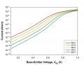
So, as a challenge to myself I decided to try to build a simple "voltage" amplifier circuit. The idea would be that by making small voltage adjustments on the base pin I would expect to get full (or close enough) range on the collector or emitter. For example by varying voltage from 0-0.6 V on base pin I would get 0 to 5V output voltage (assuming I am using 5V power source).
I am currently a bit stuck on trying to read and understand datasheets. For example https://www.mouser.com/ds/2/149/BC550-888526.pdf
One question that is a bit unclear is that if transistor becomes like a closed switch when you apply some specific voltage to the base pin why does it have some collector-emitter saturation voltage - Vce(sat)? My only guess its the voltage drop when transistor is in saturation mode and it still may have some resistance. Is that what it is? If that is so, would not source voltage affect those values?
Second thing is the base-emitter voltages (on and saturation). On voltage sounds like when transistor starts conducting current on collector-emitter. Anything below will make it "off". If that is true then how come saturation voltage is pretty much the same. Does it mean these types of transistors will make a bad amplifier and may be really be used as a switch mostly?
Can someone comment whether my thinking is correct or makes sense or where I am getting a bit off?
Also, it would be nice to know if my so-called challenge is doable at all?
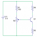
I have attached the basic schematics I am thinking that may work.
So, as a challenge to myself I decided to try to build a simple "voltage" amplifier circuit. The idea would be that by making small voltage adjustments on the base pin I would expect to get full (or close enough) range on the collector or emitter. For example by varying voltage from 0-0.6 V on base pin I would get 0 to 5V output voltage (assuming I am using 5V power source).
I am currently a bit stuck on trying to read and understand datasheets. For example https://www.mouser.com/ds/2/149/BC550-888526.pdf
One question that is a bit unclear is that if transistor becomes like a closed switch when you apply some specific voltage to the base pin why does it have some collector-emitter saturation voltage - Vce(sat)? My only guess its the voltage drop when transistor is in saturation mode and it still may have some resistance. Is that what it is? If that is so, would not source voltage affect those values?
Second thing is the base-emitter voltages (on and saturation). On voltage sounds like when transistor starts conducting current on collector-emitter. Anything below will make it "off". If that is true then how come saturation voltage is pretty much the same. Does it mean these types of transistors will make a bad amplifier and may be really be used as a switch mostly?
Can someone comment whether my thinking is correct or makes sense or where I am getting a bit off?
Also, it would be nice to know if my so-called challenge is doable at all?
I have attached the basic schematics I am thinking that may work.
Attachments
-
 14.1 KB Views: 22
Last edited: