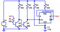
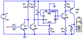
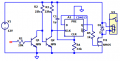
I am gona buy cd4013 becose 7474 can only uostand an input voltage maximum 7 vdc and my input is 12 so it will fry it and cd4013 i think it can use 15vdc and thats perfec for my aplication beacose i need to power 12v relay ofcorse i will put transistor beacose the chip can't power the relay and for the rest pin i will need the circuit when i powerit to stay off and when senses pulse of 5 vdc than to turn on
I am gona buy cd4013 becose 7474 can only uostand an input voltage maximum 7 vdc and my input is 12 so it will fry it and cd4013 i think it can use 15vdc and thats perfec for my aplication beacose i need to power 12v relay ofcorse i will put transistor beacose the chip can't power the relay and for the rest pin i will need the circuit when i powerit to stay off and when senses pulse of 5 vdc than to turn on
To drive a relay, if you know the coil current, check the sink capability of the CD 4049 hex inverter when it is running on 12 or 13 volts. All six in parallel might be enough.
ALSO, be sure to avoid excess V to those CMOS devices. The published limits are true!
There are a lot of circuits that run on 12 volts. What concerns me is when people think of a car electrical system. Though it's a 12 volt system it can see voltages as high as 14.4 volts after engine startup. What's more, car electronics are notoriously noisy. I learned that a long time ago when I built a 12 volt circuit for my car. It lasted about 2 weeks before it was dead. Back then I understood very little about electronics and what I was learning I got from magazines. They helped a lot, but there was a lot not discussed. So if this is a circuit you're building for a car - beware of transient spikes that can fry your CMOS circuitry.
To drive a relay, if you know the coil current, check the sink capability of the CD 4049 hex inverter when it is running on 12 or 13 volts. All six in parallel might be enough.
ALSO, be sure to avoid excess V to those CMOS devices. The published limits are true!
OK, and if the relay takes more than about 50mA that is the way to go. BUT using one IC with no extra components is NOT more complicated than using an FET or MOSFET or even a bipolar transistor.
OK, and if the relay takes more than about 50mA that is the way to go. BUT using one IC with no extra components is NOT more complicated than using an FET or MOSFET or even a bipolar transistor.
In that case my suggestion will not work. That is why I added the qualifiers about the relay current. With a relay like that you do need to include protection against inductive spike voltages, but at the same time you need to avoid slowing down the contacts opening to preserve contact life.
In that case my suggestion will not work. That is why I added the qualifiers about the relay current. With a relay like that you do need to include protection against inductive spike voltages, but at the same time you need to avoid slowing down the contacts opening to preserve contact life.

 Facebook
 Google
 GitHub
 Linkedin