Need help with with darlington pair setup to power 555 timer circuit

Thread Starter

robnoper

Joined Mar 5, 2019
24
Capture2.PNG

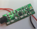
I have the above circuit roughed out and seems to work but have problems with the Q2 transistor blowing.
the circuit is powered by 12V and a sounder circuit connected to H3.

1.5v is used to turn on the Darlington pair which in turn powers up the timer circuit.
Pin 3 of U1 gets triggered and then makes alarm sound for set time.

Is the Darlington pair correct or any better way of doing it.
I can get circuits working but im no electronics engineer but just need a helping hand.

Thanks
 

AlbertHall

Joined Jun 4, 2014
12,345
Q2, when switched on, will short circuit the power supply and draw lots of current. That is why Q2 keeps blowing.
Do you want the '555 to be powered when the 1.5V input is present, or when it is not present?
 

Thread Starter

robnoper

Joined Mar 5, 2019
24
Q2, when switched on, will short circuit the power supply and draw lots of current. That is why Q2 keeps blowing.
Do you want the '555 to be powered when the 1.5V input is present, or when it is not present?
I want it to be powered on when 1.5v is present
 

AnalogKid

Joined Aug 1, 2013
10,986
LED2 is backwards.

Albert's suggestion will work fine with the information you have given us so far, but you have not given us enough information for a complete solution. We need to know more about what is driving the Trigger input and what to 555 output goes to. The issue here is grounding. Switching the ground to a circuit to turn it on and off could cause problems because while the circuit will not run, its inputs and outputs still are connected, and +12 V is roaming around inside the 555 and could appear in some form on external pins.

A safer (but still not perfect) way is to switch the +12 V to the circuit and leave the ground connected, but this changes the logic polarity of the enable signal, requires a PNP transistor, etc.

ak
 

Thread Starter

robnoper

Joined Mar 5, 2019
24
the trigger is a momentary trigger of a voltage to start the 555 timer. That works fine.
Thanks for pointing out the LED, told you I wasn't a electronics engineer but always willing to learn. :) Will adjust that.
The sounder board works off 12v and doesn't draw that much current and comes out of this box and spec says about 300ma

https://www.amazon.co.uk/SODIAL-Str...coding=UTF8&psc=1&refRID=YV5F6HRT4TACXP2RMZ5M
 

Attachments

Thread Starter

robnoper

Joined Mar 5, 2019
24
Can you suggest a suitable PNP circuit with transistors etc that will suffice? you guys have been a great help so far.
 

AnalogKid

Joined Aug 1, 2013
10,986
Albert keeps getting in ahead of me.

My vote (also) is to use the 555 to drive an external power transistor that then drives the sounder. Best way to do this is to change the connections to the sounder - connect the red lead directly to the +12 V, and have the transistor switch the black lead connection to GND. MOSFETs are nice but I prefer good old bipolar power transistors for this kind of application. TIP 29 and TIP31 are very common for this, and the 2N3055 is overkill but fine if you already have one lying around.

555 pin 3 to (330 or 470) ohm resistor
Resistor other end to transistor base
Transistor emitter to GND
Transistor collector to sounder black lead
No need for a heatsink

Caution - the transistor tab or case is tied to the collector. Don't let it touch any conducting surfaces (metal box, flying wire, etc.)

ak
 

Thread Starter

robnoper

Joined Mar 5, 2019
24
So I have made changes and thought would run by you guys..

Will check out running it through the 2n2222 but last time it didn't provide the power.

Any feedback and suggestions and modifications to the circuit welcome.
The 555 timer works fine turning sounder on and off.
 

Attachments

AlbertHall

Joined Jun 4, 2014
12,345
Will check out running it through the 2n2222 but last time it didn't provide the power.
You will need to reduce the value of R3 to something like 100Ω to get enough base current for the 2N2222.

Is it your intention that Q1 should also switch the IR transmitter and receiver (as your schematic does)?
 

Thread Starter

robnoper

Joined Mar 5, 2019
24
You will need to reduce the value of R3 to something like 100Ω to get enough base current for the 2N2222.

Is it your intention that Q1 should also switch the IR transmitter and receiver (as your schematic does)?
Yes when the programmable timer gives its 1.5v to the Q1 then it should turn on both IR circuits and 555 timer circuit ready to be triggered.
The programmable LCD timer display goes dim when I change the Q1 resistor too much and that suggests its Q1 is drawing too much current?

Also could do with finding out where to get the programmable timer from or a schematic to make one from scratch. Picture attached.
 

Attachments

AlbertHall

Joined Jun 4, 2014
12,345
OK, so you may still need a Darlington. Leave the 2N2222 as it is but disconnect the 10k from the base and connect it to the base of the extra NPN transistor. Connect the emitter of the extra transistor to the base of the 2N2222 and connect the two collectors together.

It is possible that the 2N2222 may get warm in this circuit. If it does then there is a modification that will keep it cooler.
 

Bernard

Joined Aug 7, 2008
5,784
If there are no other connections to the clock, then it looks like the output Z is around 8k; so we need a high Z input stage
inverter feeding a N ch FET which drives either a power darlington transistor or a power N ch FET. Or change the clock.
What are the requirements for the clock ?
 
Top