 Facebook
 Google
 GitHub
 Linkedin
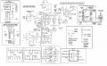
It might work, the invertor oscillator is not where the stress will be. That MOSFET is going to get hot, very hot, so heatsinking will be required. It is also drawn in such a way as which lead is which is ambigous, which is usually a way to connect it backwards and blow it out. The invertors are outside the norms for drawing schematics, but close enough for most people to figure them out.
You will also need a resistor between the gate and the output of the 40106, say 100Ω to allow the MOSFET to switch cleanly.
Given all the foriegn language around that schematic I'm betting you didn't draw that sucker. Care to share the source?
There is a good chance the 40106 is a bit weak on the drive, but like I said the MOSFET and the coil it is driving is what is going take most of the stress, followed by the power supply. That coil will be drawing many amps, probably in excess of 10 amps, thought the exact number is hard to predict.
BeenThere is right about that high voltage. You are in the realm of one minor mistake and you will fry, these kind of voltages are not to be messed with.
BTW, a 555 can output up to 200ma (0.2A), while one output of the 40106 is rated for several µa (0.000002A).


")


