Need help with the wiring.

Thread Starter

Saker

Joined Aug 19, 2024
12
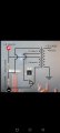
This circuit made me a little bit confused. I get it that I should solder the negative input to one end of the resistor. But the other? I really need someone to explain to me exactly how to connect the resistors. I appreciate any help.
 

Attachments

boostbuck

Joined Oct 5, 2017
1,043
The other end of that resistor connects both to one end of the second resistor AND to one side of the flyback winding on the transformer. The other end of the second resistor connects to positive input, as does one side of the transformer primary. And so on.

Without commenting on the design of the circuit itself, the diagram seems pretty clear.
 

wayneh

Joined Sep 9, 2010
18,104
In case this is what is confusing you:
1729984397851.jpeg
The curve indicates where the wiring does NOT make a connection to the horizontal, straight wire. Conventions vary but a solid black dot there would typically indicate a connection. A simple crossing without a dot is ambiguous and should probably be considered a non-connection, like the curve indicates clearly, but it's best to use the context of the surrounding circuitry to make that determination.

In your diagram, a simple crossing such as the one between the two resistors, indicates a connection.

If something else is not clear, just ask.
 

Thread Starter

Saker

Joined Aug 19, 2024
12
The other end of that resistor connects both to one end of the second resistor AND to one side of the flyback winding on the transformer. The other end of the second resistor connects to positive input, as does one side of the transformer primary. And so on.

Without commenting on the design of the circuit itself, the diagram seems pretty clear.
One more question. Is it ok if I connect one end of the 220 resistor to the Primary coil and then connect the positive power supply to the primary coil?
 

MisterBill2

Joined Jan 23, 2018
27,508
This IS a comment about the circuit design. It is potentially rather dangerous, and also not very likely to work, and if it did work, to not last very long before the transistor overheats and fails.
Is there any description with that circuit??
Where did it come from??
 

Thread Starter

Saker

Joined Aug 19, 2024
12
This IS a comment about the circuit design. It is potentially rather dangerous, and also not very likely to work, and if it did work, to not last very long before the transistor overheats and fails.
Is there any description with that circuit??
Where did it come from??
From the Plasma Channel video when he makes a high voltage power supply
 

MisterBill2

Joined Jan 23, 2018
27,508
At least the first alternate circuit puts way too much positive base bias on the transistor. The oscillator will only work if the signal from the feedback winding is able adequately affect the collector current in the correct direction. And the drawing gives no direct clue as to the relative winding polarities. One way may work, the opposite polarity will not work.
 

Thread Starter

Saker

Joined Aug 19, 2024
12
At least the first alternate circuit puts way too much positive base bias on the transistor. The oscillator will only work if the signal from the feedback winding is able adequately affect the collector current in the correct direction. And the drawing gives no direct clue as to the relative winding polarities. One way may work, the opposite polarity will not work.
any possibile alternative?
 

boostbuck

Joined Oct 5, 2017
1,043
In the original diagram it was held at about 1 volt through the voltage divider, but in Tony's revised diagram it is connected directly to 12V supply through the 220 ohm resistor, which will provide ~50mA(!) base current.
 

Tonyr1084

Joined Sep 24, 2015
9,744
And the drawing gives no direct clue as to the relative winding polarities.
Good point.
Haven't you reversed the flyback role?
Not my drawing.
In the original diagram it was held at about 1 volt through the voltage divider, but in Tony's revised diagram it is connected directly to 12V supply through the 220 ohm resistor, which will provide ~50mA(!) base current.
Oops. Yes, you're right. I will have to delete those drawings straight away.
 
Top