Need help with shielding wires on a project.

ronsoy2

Joined Sep 25, 2013
71
Hello!
Why not go with a Dragonlink V3 for your control? The V3 has a built-in spectrum analyzer that lets you directly see the noise floor with all your stuff activated. If you get noise, you start unplugging stuff until the noise disappears, and then work on that. I fly out 13 miles with my GODISCOVER with the dragonlink V3 and a 1 watt video transmitter on the plane at 1280mhz. The noise floor is below -105 dbm with everything plugged in and operating. I don't have any shielding on anything at all. It is not necessary if the equipment is proper.
Your servos are not the noise generators. Look at your cameras. Some have processors that generate horrible harmonics in the 433mhz band. Remember, you are looking at fractions of a microvolt signals. The camera processor has 3-5 volts of hash generating electronics with no shielding at all. Use cameras that are expressly designed for long range FPV. (see GETFPV.COM)
You are not going to have much luck trying a hit and miss approach. (too many crashes) You need the spectrum analyzer. If not the built-in function of the Dragonlink, a good HP analyzer.
Don't fly if you don't have a computer assisted RTH (return to home) function. Too expensive to lose it all! (Eagletree Vector is one of the best)
 

windadct

Joined Feb 25, 2013
4
Somewhat surprised you have not gotten a little better info - or more complete. Here is my 2c. A good ground / shield scheme is a lot about best practices and a bit of art. If this is actuallt a product -- not a one off build, it would be wise to really pay attention to the the grounding and shielding scheme.

As a general rule you shield wiring runs from the Source outwards, and you only terminate the shield at the source, not the destination. So you do not create any LOOPS, for long runs, you may use a capacitor to connect the "far end" to the local ground to allow noise to pass but prevent a current loop. The overall scheme should look like a radial pattern if you draw every conductor including the shields. For a Battery powered system you have some more flexibility where you make your ultimate chassis bonding point ( eg - it could be close to the uC).

Start by identifying the types of circuits you are dealing with, I would divide into Power, Digital and Analog ( Sensors - even if a pulse train like an encoder treat it like analog)

Power - since most of your radiated noise in a switched power device comes from the power circuits, shielding the power leads helps to "contain" the noise. Generally the power systems themselves do not have a problem with the ( are interfered by) noise. However - if you DO shield the power runs, and terminate them on both ends you will see a lot of noise on the ground plane due to circulating current in the power shield generating a mess....

Digital and Analog can be handled the same way but should be kept separate. ( don't, or try not to, have analog and digital signals in the same shielded run)

Generally if a 2 wire circuit ( digital may be more) - 2 wire twisted pair, and shield. The shields of multiple signal runs should be terminated to a common point as close as possible to the source of power for that signal. For example to the GND connection on the uC PCB, but NOT back to the shield of the power run from the Battery to the uC. ( Yes - ultimately all of these connections come together at the battery, but it is EMI noise and circulating currents that we need to avoid - not the same as seeing this all as one electrical point like you would in DC circuit analysis)

So -- what about items multiple interconnections? Consider a motor driver, with a direct connection to the battery, to the uC, and a motor encoder.

Battery (-) to Chassis Ground
(+ & -) to Motor Controller -- if shielded the shield is connected to the Chassis Ground point and run to but not connected to the MC board.
(+ & -) to uC - in shielded cable, shield connected to the Chassis ground.

uC ("n" signals & Gnd ) in a shielded cable to the Motor Controller digital inputs. Shield is connected to the uC Gnd, and not terminated to the MC. Here is a place to pay attention! Are the uC and the MC Ground the "Same" ? for larger power the "power ground" and the "Signal ground" could be different. n= the digital connections to the motor controller.

Motor Controller ( + & -) run to the motor. If shielded shield connected to the MC Gnd. Important to note that the MOTOR "-" is NOT ground anymore since the MC will reverse + and - for directional motor control.

Encoder Feedback - the MC may have feedback connections, and pass them through to the uC - if so I would run direct from the encoder to the uC and terminate the shield at the uC. (not at the encoder end). If the MC processes the feedback signal then run the connection from the MC to the Sensor - Shield to MC GND.
 

#12

Joined Nov 30, 2010
18,224
Somewhat surprised you have not gotten a little better info - or more complete.
Most of the hot-shots here are retired...like me...and I'm an analog guy who mostly does, "back to the basics" or, "when you can do it with 8 to 15 discrete parts instead of programming an MPU".

Basics are good, but the world is moving faster than I am this year.:oops:

So, same request. Stick around. If anybody here knew what you know, it would have arrived in less than 2 weeks.
 

Thread Starter

born2dive00

Joined Oct 24, 2016
285
Somewhat surprised you have not gotten a little better info - or more complete. Here is my 2c. A good ground / shield scheme is a lot about best practices and a bit of art. If this is actuallt a product -- not a one off build, it would be wise to really pay attention to the the grounding and shielding scheme.
Hello Windadct.
Thank you for your reply it is much appreciated.
What I was thinking envisioning

Step 1. I was to take a standard servo, put it in a metal box, put a cover on it, cut a hole for the joint of the servo arm to push the push rod thru. I was then thinking of taking some brass window screen solder it to the cover and over the hole attaching it to the metal push rod. I believe that this would create a faraday cage to prevent EM and RF interference entering the servo.
Step 2 remove existing servo wires and install braided shielded wire on all 3 lines.
Step 3. solder a small capacitor between the Signal wire and power+ line, between the power +wire and ground, and another between the signal wire and ground.
Step 4 Connecting the cores of the shielded wire to where the old servo wires were connected.
Step 5 take all the shielding from the 3 wires and solder them to the metal box enclosing the servo.
Step 6 Take the receiver and use double sided foam tape to prevent any conductive contact with the outside faraday cage.
Step 7 take brass window screen and create an envelope and slide the receiver inside (the tape would keep it from touching the sides)
step 8 solder the ends of the envelope closed making a faraday cage.
Step 9 Take the loose end of the servo wire, plug it in to the receiver.
Step 10 Take the shielding around the servo wire and solder it to the brass screen.
Step 11 Take the remaining electronics Receiver, transmitters, batteries and other boards and do the same process, connecting them first then solder the shielding to the screen.
Step 12 Connect the battery to the circuit, then take a wire from the negative lead of the battery and solder it to the screen at only 1 point.
Step 13 run the antennas thru the brass screen out of the faraday cage.

Would this work???

I appreciate Ronsoy's thought, but I need to be preventative not reactive. I am trying to get the Db noise floor as low as possible, this changes based on locations. Ergo i figure if I shield everything then it should prevent external interference which affects the range.

The questions if the above would work is

1. how do I get the SMA antennas out thru the shielding so that it can pick up the signals? there are 3 antennas with sma connections. Do I ground the sma connector to the screen or do I simply insulate them then spread the screen large enough to get the sma connector thru then pushing the screen back into position around the coaxial cable??

2. The wires are braided shielded wires 18gauge core insulated, braided shield, and outer insulation. I can not seem to find single wire in 18 gauge multi strand core wire that is double shielded, i.e.1 wire 18 gauge insulated, foil shielded, insulated, braided shield, outer insulation.

So what i was thinking was to take alumumimum tape and tape the outside of the single braided shielded wire to protect against low EMI. Would this work?? The center core wire is multi stranded and twisted.

3. If question would not work would there be advantage to braid the shielded wires together? seeing that they are already shielded?

4. From what I have read the Electronic speed controllers, DSLR cameras, and servos create noise both on the voltage side, and the current side. I know by installing capacitors on the lines helps remove voltage noise (if I am not mistaken) and wrapping the wires thru ferrite rings helps remove current noise.

So again does wrapping shielded wire thru ferrite rings work? Or will the shielding prevent it from working?

5. I have been also told I don’t need to use ferrite rings or capacitors that LC filters connected between the battery and the equipment will fix all the potential problems.

So this brings me back to what do I use to eliminate internal electrical noise.

I was thinking of using capacitors on all servos, LC filters on the motors, onboard charging system (uses a brushless outrunner motor in reverse) on the Digital cameras on the power lines of the transmitters and the receivers. I was thinking of using ferrite rings only on the analogue flight cameras.

Can you advise as to what is needed where, how far from certain equipment. I rather go overboard in preventing possible interference rather than not doing enough.

Any information ideas and help you can give me would be great!!
 

Thread Starter

born2dive00

Joined Oct 24, 2016
285
Hello! QUOTE]
Hello Ronsoy, I appreciate the thought on using the dragon link. I am glad that you are having good luck with the system. But there are 3 problems that we have run into with that system, 1st is the power to distance it delivers is too weak, and second reliability 3rd field repairs.

For this project we are using the EZUHF (more dependable reliable) for closer ranges less than 20 miles for longer distances we hand it off to the Scherrer 433 long range transmitter and receiver with a 8w booster. This pushes our ranges at the game reserve parks out to distances often close to and exceeding 100 kilometres 70 miles... The sensitivity on the dragon link is not sufficient for these distances. The best we have been able to get is out to 40-55 miles before there was too much interference and signal drop. There is one reserve that we are working with where they need to get it out to 100 miles.

The other problem with the dragon link is it is not as reliable as the ezuhf and Scherrer, systems. We have had 2 of 5 units arrive with or died shortly after power up. If an electrical part fails in the Dragon link the system is dead there is no repairable components in the field. The parts that are likely to fail in the ezuhf and scherrer are field repairable, often salvaging parts from old electronics.
 

kiloamp

Joined Apr 7, 2013
4
I don't often chime in but for em shielding I use old VHS tape and just wrap around whatever to completely cover it, no grounding needed. I first thought of this for florescent lamp driver transformer, wrapped it in the tape and no electro magnetic radiation emitted. I think this should work for all kinds of projects. Best part is that VHS tapes are usually free these days.
 

Kermit2

Joined Feb 5, 2010
4,159
You are over thinking this a tiny bit
Just keep all power carrying wires away from control wiring.
Use your copper screen and wrap the wire runs, then anchor them. Wax thread (like floss)can be used as an overwrap to keep the screen in place.
The ground on the digital/uP control section should only be connected in common with your other ground wires at the point where battery power is delivered to the drone.

Then add the grounding connection wire to the screen at the battery end only as previous members have instructed
 

Thread Starter

born2dive00

Joined Oct 24, 2016
285
Is it possible that someone can draw a diagram of what I need to do here. I understand keeping the signal wires separate from the power wires.
This air frame has thus cost over $10,000 for this project I care not leave anything to chance due to a glitch caused by a RFI or EMI.
The control rods are metal and over a meter long, some of the leads going to the servos are about 2 meters long. As I understand (my very simple understanding) these wires a and control rods can act as antennas introducing External RFI into the system. I might be wrong about this.

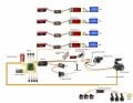
I have uploaded a fairly complete systems diagram that I need to shield. The yellow wires are the signal wires, orange wires are power + brown wires are power -

If someone can please draw me a diagram I have difficulty in putting some of your words and concepts into a image.
Please let me know
Brad.
Untitled.jpg
 
Top