I must say that although a supercap could do this easily and in a small space, the charging circuitry would be more complicated and the advantage over a small secondary cell (or, as @MrChips points out even a primary one) is hard to find.
Assuming I wanted a long term solution, avoiding the need to replace dead cells, I woud probably use something like an LIR2032 cell and an photointerrupter rather than a mechanical switch. Since the circuit will be connected to the charging supply when it is closed, the photointerrupter’s standby current will not drain the cell.
I would probably just go with a primary (or externally charged secondary cell, though. and the mechanical switch. This little boost converter*, this CoB LED strip cut to length, and whatever limit switch arrangement is most suited would be a cheap and cheerful solution quickly implemented.
*It would be necessary to remove or disable the power indicator LED, a trivial thing.
I must say that although a supercap could do this easily and in a small space, the charging circuitry would be more complicated and the advantage over a small secondary cell (or, as @MrChips points out even a primary one) is hard to find.
Assuming I wanted a long term solution, avoiding the need to replace dead cells, I woud probably use something like an LIR2032 cell and an photointerrupter rather than a mechanical switch. Since the circuit will be connected to the charging supply when it is closed, the photointerrupter’s standby current will not drain the cell.
I would probably just go with a primary (or externally charged secondary cell, though. and the mechanical switch. This little boost converter*, this CoB LED strip cut to length, and whatever limit switch arrangement is most suited would be a cheap and cheerful solution quickly implemented.
*It would be necessary to remove or disable the power indicator LED, a trivial thing.
I actually don't understand how the circuitry would differ between a battery and a capacitor. Both needs to be isolated from the led and charging when the drawer is closed and both needs to be connected to the led when the drawer opens. According to me the battery method will just need extra components for the charging. Am I correct in my thinking?
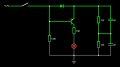
Here is a rough idea of something that might work with super caps (which really ain't that super, BTW)
Super caps tend to have really low working voltage, here I have 2 X 2.7 V parts in series to support 5V, the LED regulator provides a 20 mA constant current, this will charge the caps to 2.5 V each, and stay there. The diode keeps the transistor off until the power disconnects, then the LED with light up, for a short while.
It will take eons to charge, but do you actually care? drawers are usually closed for long periods.
Here is a rough idea of something that might work with super caps (which really ain't that super, BTW)
Super caps tend to have really low working voltage, here I have 2 X 2.7 V parts in series to support 5V, the LED regulator provides a 20 mA constant current, this will charge the caps to 2.5 V each, and stay there. The diode keeps the transistor off until the power disconnects, then the LED with light up, for a short while.
It will take eons to charge, but do you actually care? drawers are usually closed for long periods.
It is important to understand that at some point fairly early in the discharge curve the voltage will drop below the level needed to drive current thru the LED to produce useful light.
It is also useful to consider driving the LEDs with more than the 20 milliamps traditional current, given that the on time will be relatively short, and that a reduction in the LEDs 20,000 hour lifetime is not going to matter for this application. A typical nicad AA cell will probably outlast the wear-life of the drawer it is illuminating, unless it is abused electrically.
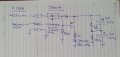
Wow the circuit you gave me works great. Here attached is the circuit that I simulated. Without the current regulator the capacitors charge in less than a micro second. I am unsure if that is safe. The led voltage takes 5min to drop from 2v to 1.8v which is awesome. Thanks again for your help but I still have 1 last question. How can I properly ground the drawer?
I don't think grounding it on the slide rail will be enough?
(1) you will over-voltage the caps, 6 volts is too much.
(2) there must be a current limiting mechanism, otherwise you are just shorting the power supply into the discharged caps.
(3) it takes at least 3.2 volts to light the white LED, all the voltage below that is unusable.
Only between 5 and 3.2 V will you get any light. (this is one reason that caps suck for this application)
(4) as long as you use an isolated mains PSU - "grounding" is meaningless here? why do you think anything has to be grounded? - except maybe the frame of the power supply?
Simulators are great for misleading yourself, like thinking the caps will charge in 1uS, that's not happening in the real world..
(1) you will over-voltage the caps, 6 volts is too much.
(2) there must be a current limiting mechanism, otherwise you are just shorting the power supply into the discharged caps.
(3) it takes at least 3.2 volts to light the white LED, all the voltage below that is unusable.
Only between 5 and 3.2 V will you get any light. (this is one reason that caps suck for this application)
(4) as long as you use an isolated mains PSU - "grounding" is meaningless here? why do you think anything has to be grounded? - except maybe the frame of the power supply?
Simulators are great for misleading yourself, like thinking the caps will charge in 1uS, that's not happening in the real world..
Use two TL431's in place of the 125 ohm resistors, these balance the voltage on the caps, preventing over voltage, and they will not waste power when the light is on, nor will they slow the charging.
What I like about this idea is that it's a permanent solution, batteries are temporary solutions, always failing when you need them most.
This thing could last as long as the house- trouble free.
Use two TL431's in place of the 125 ohm resistors, these balance the voltage on the caps, preventing over voltage, and they will not waste power when the light is on, nor will they slow the charging.
What I like about this idea is that it's a permanent solution, batteries are temporary solutions, always failing when you need them most.
This thing could last as long as the house- trouble free.

 Facebook
 Google
 GitHub
 Linkedin



 Thanks for the Help