Need Help with Heat Buzzer Project

Thread Starter

multisandstorm

Joined May 11, 2018
2
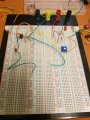
I posted here yesterday and I took the advice of the people and designed something on Ltspice to make my design more clear. The premise of the project is to use a thermistor and apply contact so the resistance of it goes down and it makes the led light up. With that in hand, it needs to create a signal that'll produce noise to a speaker.
upload_2018-5-12_21-39-11.png
The image is the breadboard I have below. I am confused on where to attach my thermistor and my speaker. I am also confused on where to put my 160K resistor.
P.S the op-amp I'm using is CA74ICE
 

Attachments

ebeowulf17

Joined Aug 12, 2014
3,307
I'll start by saying that there are loads of op amp configurations that I'm not familiar with - I still have an awful lot to learn. Having said that, I have no idea what's going on with U2 or any of its connections. Why are you powering an op amp from the output of another one?

As for U1, I'll neither confirm nor deny the specific resistor values, but the basic concept up until the output of U1 looks reasonable to my eyes. Everything after that is confusing to me.

If you want to light an LED, why not use a series resistor to either ground or supply voltage (depending on whether you want it lit when U1 output is high or low.)

Are you sure your op amp is CA74ICE? I tried googling that, and it comes up with a "connectorized" part (first time I've seen that term,) not a DIP, through-hole IC like you appear to have:
https://cdn.macom.com/datasheets/A74_SMA74.pdf

In order to advise you on driving the buzzer, we'll need to know what buzzer you want to use. Some have an internal oscillator and simply need to provided DC voltage to operate, while others require an external oscillator to drive them.
 

crutschow

Joined Mar 14, 2008
34,468
Normally you shouldn't use the output of one op amp to power another.

V1 needs to be connected to ground.

The OP07 won't drive an 8Ω load.

The op amps need connection to a supply.

Why didn't you simulate it?
 

MisterBill2

Joined Jan 23, 2018
18,590
It is certainly true that driving the power terminal of an op-amp with the output of another op-amp is seldom seen. In fact I have never seen it. I understand the logic, though. But using an op-amp as a comparator is not the best choice, and I don't recommend anything from the 741 family for current use, because there are so many devices both better and cheaper.
Probably the U1 op-amp will oscillated as the setpoint is passed, but the results will not be satisfactory.
I suggest studying some of the older op-amp general applications circuits to see how others have produced circuits that work. "schematics for free" is a site that has a lot of interesting circuits, although not much explanation about how they work.
 

ebeowulf17

Joined Aug 12, 2014
3,307
Ohhhhh, is U2 set up as the oscillator to drive the buzzer? One of these days I'm going to have to learn some oscillator circuits so I can recognize them when I see them!

So maybe one thing that's missing is a BJT or MOSFET between U1 and U2 so that U1 can control power to U2 without having to directly source the power?
 
Top