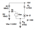
Need help with gain of a BJT amplifier, circuit.

Status
Not open for further replies.

LvW

Joined Jun 13, 2013
2,035
Making re zero gets the gain to the neighborhood of -11;
..............................
Leaving out re and them making an arithmetic mistake seems to me the likely explanation.
Yes - I agree. Most likely, the author did neglect (forget?) the influence of re=1/gm.
Surprisingly, it happens relatively often that somebody uses the simplified gain expression "RC/RE" - perhaps without knowing that this is an acceptable approximation for the case RE>>1/gm only .

(Remark: I do not like at all the term "re" instead of "1/gm". Rather often I have seen that there was a confusion between an external feedback resistance RE and re=1/gm. This is, in particular, a problem when a capital letter ("Re") is used and not the symbol for a dynamic resistance ("re").
More than that, the unit of "1/gm" is V/A, however, it is not really a resistance -some people even call it "internal emitter resistance". Instead, it connects the voltage between B and E with a current between C and E - surely not a two-pole element which we may call "resistor").
 
Last edited:

LvW

Joined Jun 13, 2013
2,035
I suppose you could call it a "transfer resistor": https://www.quora.com/Why-are-transistors-called-transistors
Yes - that sounds logical because it is the invers of a "trans(fer)conductance.".

In this context, here are some more detailed informations explaining the naming of the transistor (found in the Internet):
(1)
"Bell Labs decided to unveil the invention on June 30, 1948. With the help of Texas Instruments engineer John Pierce, who wrote science fiction in his spare time, Bell Labs settled on the name "transistor"-- combining the ideas of "trans-resistance"
with the names of other devices like thermistors.
"

(2)
"They'd built the device, but they didn't have a name. (Point-contact solid state
amplifier isn't exactly catchy.)
Walter Brattain wanted something that could capture the feel of the amplifier in a single word. He asked around in the lab but no one had come up with anything.
One day in May as he was walking down the hall thinking about the problem, he bumped into his friend, John Pierce.
Now, Pierce had a way with words -- he would go on to become an
accomplished science fiction writer -- so Brattain asked him if he had anythoughts.
Thinking out loud, Pierce pointed out that just as the vacuum tube
had transconductance, the new amplifier had the electrical property of
transresistance.
He also knew that a number of electronic devices had come out recently
with names, such as varistor and thermistor.
How about 'transistor.' he suggested? And Brattain responded: "Pierce, that's it!"
 
Last edited:

MrAl

Joined Jun 17, 2014
13,764
There was a slight misunderstanding (caused by my unclear words).
Of course, there will be always a difference between hand calculations and Spice simulations - I think, it is not necessary to explain why.
But with my comment regarding the "small difference" I was referring to the small deviation between Jonys and my hand calculations (both of us did not take into account the finite output resistance of the BJT, which will further decrease the gain)
Hello there,

There will be no difference between the spice simulation and the hand calculation if the same models are used. If there is even one small difference in any one of the models then the results will not match exactly.
For example, i typically get matches of 6 or more significant figures and that is only because i dont ask to see any more in the spice simulation. So for example if i calculate 1.234561 i will see a sim result of 1.23456. If the result happens to be the ratio of two integers though i might see the exact value, for example 123/100 will show as 1.23 in the sim.
Just to note, differences of 0.1 or even 0.01 in such a simple circuit like this one means one or both persons did something wrong when the result is around 10 or so. So if one person gets 10.11 and the other gets 10.20, somebody did something difference :)
Float errors which cause rounding and truncation usually come out to less than 1e-8 for simple problems like this one.

This is one problem symbolic solutions do not have if they are completely symbolic and dont involve any arbitrary constants. For example, if someone gets v=E1*R2/R3 then the other should darn well get the same result :)
 

MrAl

Joined Jun 17, 2014
13,764
Hello to all, here are my results - derived by hand calculation using classical methods.
In addition I have performed a Spice-analysis (BC548).
For my opinion, during calculation of the DC bias pont the influence of the BC548 current gain (other than B=300) plays no great role because of the negative feedback (RE=570 ohms).
I think, the most "critical" point is finding the correct DC collector current and the corresponding transconductace gm.
All other steps are - more or less - standard procedures.

Results (Simulation in brackets):

IE=1.675 mA (Sim: 1.785mA)
IC=1.67mA (Sim: 1.776 mA)
Transconductance gm=0.0642 A/V
Vbasis=1.605 V (Sim: 1.696 V)
Input resistance at the base node (incl R1||R2): 9.1 kOhm
Total gain: A=-9.78 (Sim: -9.355).

So - I am very close to Jonys results. At the moment, I don`t know the reason for the small difference.
Question to Jony: Is it correct that your value for Rth does not yet contain the small base current IB=IC/300 ??

That means: It seems to be clear that the gain magnitude is below A=10.
Hence, the "book answer" with "-11.3" seems to be wrong (no surprise...each book contains errors).
Hi,

First, what made you think they wanted you to include 're'?

Also, i get a different value for the gain in simulation.

In simulation with re=25/iE i get:
-9.916

and in symbolic calculation (with values added later) i get:
-9.913

This agree to within about 3 parts in 10000 so i cant help but think this is correct. I could have gotten the sim result more accurate if i took more time.

This is using what you guys had been using i guess, which is re=25/iE.

For reference, the symbolic solution to 're' i get is:
re=
(K*(Bp1*R2*RE2+Bp1*R1*RE2+Bp1*R2*RE1+Bp1*R1*RE1+R1*R2+Rb*R2+Rb*R1))
/(Bp1*(E2*R2-K*R2-E3*R2-K*R1-E3*R1))

where Bp1=Beta+1, E3=Vbe, E2=Vcc, Rb=0, and K being the thermal voltage such as 0.025 volts.
That kind of solution means we can immediately calculate 're' for any bias condition without having to solve the entire circuit without knowing 're'.
 
Last edited:

LvW

Joined Jun 13, 2013
2,035
First, what made you think they wanted you to include 're'?
Hello, I like to answer this question - however I can`t.
I must admit that I do not understand the content an the background of the question.
Do you speak about 1/gm (=re) or about the external ohmic resistor RE=100+470=570 Ohm ? Please, help me.....
Thank you

Comment: When simulation results are presented (for the purpose of comparison) I think it makes sense to add an information about the type of transistor used - otherwise a comparison with other simulation results is not meaningful.

(For my opinion and in order to avoid misunderstandings, all of us should try to use capital letters for DC quantities (voltage, current, resistor) and small letters for dynamic/differential quantities only.)
 
Last edited:

MrAl

Joined Jun 17, 2014
13,764
Hello, I like to answer this question - however I can`t.
I must admit that I do not understand the content an the background of the question.
Do you speak about 1/gm (=re) or about the external ohmic resistor RE=100+470=570 Ohm ? Please, help me.....
Thank you

Comment: When simulation results are presented (for the purpose of comparison) I think it makes sense to add an information about the type of transistor used - otherwise a comparison with other simulation results is not meaningful.

(For my opinion and in order to avoid misunderstandings, all of us should try to use capital letters for DC quantities (voltage, current, resistor) and small letters for dynamic/differential quantities only.)
Hello again,

I was talking about 're' which is the internal emitter resistance of the transistor. This is typically around 13.5 ohms for this problem when biased.
That resistor is considered to be in series with RE1 and RE2 and is normally approximated by 25/i where i is the emitter current or 26/i with different temperature. I used 25/i this time because that was what you guys were using but i used 26/i previously.
 
Hello again,

I was talking about 're' which is the internal emitter resistance of the transistor. This is typically around 13.5 ohms for this problem when biased.
That resistor is considered to be in series with RE1 and RE2 and is normally approximated by 25/i where i is the emitter current or 26/i with different temperature. I used 25/i this time because that was what you guys were using but i used 26/i previously.
What value did you use for the emitter current iE in post #25?
 

MrAl

Joined Jun 17, 2014
13,764
What value did you use for iE in these calculations?

Hello again and thanks for the question,

I went back to post #25 and calculated 're' from that (with Rb=0 and K=0.025) and then just did:
re=0.025/iE

and then solved for iE and got:
0.0018535976

however in the simulation i got (using that value of 're'):
0.001853598

Maybe a simpler idea is to just replace 're' with a voltage source of 0.025v and be done with it because if we have the right resistance 're' and the right current 'iE' then:
v(re)=re*iE=0.025v
 
Last edited:

LvW

Joined Jun 13, 2013
2,035
Hello again,
I was talking about 're' which is the internal emitter resistance of the transistor. This is typically around 13.5 ohms for this problem when biased.
That resistor is considered to be in series with RE1 and RE2 and is normally approximated by 25/i where i is the emitter current or 26/i with different temperature. I used 25/i this time because that was what you guys were using but i used 26/i previously.
Hello and thanks for your reply.
Again - a great misunderstanding!
In post 25 you have cited me in connection with my calculation of the DC bias point and the value RE=570 ohm.
- and you have asked :...."what made you think they wanted you to include 're'?"
And now you are telling me that you mean indeed the dynamic value 1/gm=re.

May I repeat that there is a great difference between an external ohmic resistor RE and the BJT-internal (differential) quantity 1/gm (which is not an "internal emitter resistance"). While explaining my finding of the DC bias point for a given circuit, of course, the value of 1/gm plays no role at all and I am using only the existing external resistors!
Therefore, I had problems to understand your question at the beginning of your post #25.

More than that, I don`t think that 1/gm (=re) is "considered to be in series with RE1 and RE2" .
It is a dynamic quantity (inverse slope of the Ic=f(Vbe) curve) which must be used for gain calculations (for which RE2 is considered to be shorted by a large capacitor). Hence, in the denominator of the gain formula we have only the sum of 1/gm(=re) and RE1.

[Again, an example of the need to carefully distinguish between static (upper-case letters) and dynamic (lower-case letters) quantities].
 
Last edited:
Hello again and thanks for the question,

I went back to post #25 and calculated 're' from that (with Rb=0 and K=0.025) and then just did:
re=0.025/iE

and then solved for iE and got:
0.0018535976

however in the simulation i got (using that value of 're'):
0.001853598

Maybe a simpler idea is to just replace 're' with a voltage source of 0.025v and be done with it because if we have the right resistance 're' and the right current 'iE' then:
v(re)=re*iE=0.025v
In the formula in post #25, what is Rb?

Also. when you say "in simulation", are you referring to a Spice simulation? I would think Spice is going to get a somewhat different result because it will be including hoe and hre.
 

LvW

Joined Jun 13, 2013
2,035
Maybe a simpler idea is to just replace 're' with a voltage source of 0.025v and be done with it because if we have the right resistance 're' and the right current 'iE' then:
v(re)=re*iE=0.025v
Please, can you explain why and how you would replace the transconductance 1/gm(=re) with a voltage source?
 

Jony130

Joined Feb 17, 2009
5,598
however in the simulation i got (using that value of 're'):
0.001853598
So you are using re in DC calculations? Why? Since re as you know is not a DC parameter.

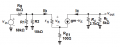
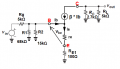
As for the BJT's small signal model. We can use the hybrid-pi model or T-model.
The small signal equivalent circuit will looks like this:

Hybrid-pi model
1.png

Where:

r_pi = β/gm

gm = Vt/Ic = 25mV/Ic


As you can see we don't have re in hybrid-pi model.

But we have re in T-model :

2.png

Where

re = Vt/Ie = 25mV/Ie = α/gm = r_pi/(β + 1)

α = Ic/Ie = β/(β + 1)

And this two models will give exactly the same answer.

So the only "uncertainty" that we can have lays in the collector current DC value and small difference in thermal voltage Vt?
Because the beta (β = 300) and Vbe = 0.65V values was given.

Do you agree?

I also add DC equivalent circuit

aa.png
 
Last edited:

LvW

Joined Jun 13, 2013
2,035
Jony - thank you for the DC equivalent circuit - because this gives me the opportunity to explain why we are allowed to use the superposition theorem for finding the DC bias point for the given values (That`s what I have done in my calculation as mentioned in my earlier post).
We have two DC sources in the circuit : Vcc=10V and Vbe=0.65 V.
Hence, it is an easy task to use superposition thereby splitting the calculation into two separate steps.
 

MrAl

Joined Jun 17, 2014
13,764
In the formula in post #25, what is Rb?

Also. when you say "in simulation", are you referring to a Spice simulation? I would think Spice is going to get a somewhat different result because it will be including hoe and hre.
Hi again and thanks again for the question(s),

There were several replies so i am replying in order of simplest to answer not in the order of the replies.

Rb is a base resistor which is not needed in most cases so set that to zero.
That could take the place of 'rb' for example, but i dont use that here.

"in simulation" i mean in a circuit simulator program. There is NO hoe and hre or anything other than 're'. That is by design because we were seeking a solution to the theoretical circuit which only included certain parameters. The model therefore is current controlled current source with gain equal to Beta, and the emitter resistor 're'.
I will explain more about my interpretation of 're' in the following replies.
 
Last edited:

MrAl

Joined Jun 17, 2014
13,764
So you are using re in DC calculations? Why? Since re as you know is not a DC parameter.

As for the BJT's small signal model. We can use the hybrid-pi model or T-model.
The small signal equivalent circuit will looks like this:

Hybrid-pi model
View attachment 165497

Where:

r_pi = β/gm

gm = Vt/Ic = 25mV/Ic


As you can see we don't have re in hybrid-pi model.

But we have re in T-model :

View attachment 165498

Where

re = Vt/Ie = 25mV/Ie = α/gm = r_pi/(β + 1)

α = Ic/Ie = β/(β + 1)

And this two models will give exactly the same answer.

So the only "uncertainty" that we can have lays in the collector current DC value and small difference in thermal voltage Vt?
Because the beta (β = 300) and Vbe = 0.65V values was given.

Do you agree?

I also add DC equivalent circuit

View attachment 165503

Hello and thanks for the reply,

Apparently your interpretation of 're' and mine are not the same.

First, you are saying that 're' is only used in AC calculations. That's true, but using the DC circuit allows us to calculate 're' in the first place. How do you think we get the value of 're' in the first place before we do any AC analysis? It's from the DC circuit. How else would we know what emitter current (or collector current in some techniques) to use to calculate this value?
Only AFTER we calculate 're' can we move on to the AC circuit,
Also, you could state how YOU calculate 're' too. I use the approximation re=0.025/iE where iE is the emitter current.
 

MrAl

Joined Jun 17, 2014
13,764
Hello and thanks for your reply.
Again - a great misunderstanding!
In post 25 you have cited me in connection with my calculation of the DC bias point and the value RE=570 ohm.
- and you have asked :...."what made you think they wanted you to include 're'?"
And now you are telling me that you mean indeed the dynamic value 1/gm=re.

May I repeat that there is a great difference between an external ohmic resistor RE and the BJT-internal (differential) quantity 1/gm (which is not an "internal emitter resistance"). While explaining my finding of the DC bias point for a given circuit, of course, the value of 1/gm plays no role at all and I am using only the existing external resistors!
Therefore, I had problems to understand your question at the beginning of your post #25.

More than that, I don`t think that 1/gm (=re) is "considered to be in series with RE1 and RE2" .
It is a dynamic quantity (inverse slope of the Ic=f(Vbe) curve) which must be used for gain calculations (for which RE2 is considered to be shorted by a large capacitor). Hence, in the denominator of the gain formula we have only the sum of 1/gm(=re) and RE1.

[Again, an example of the need to carefully distinguish between static (upper-case letters) and dynamic (lower-case letters) quantities].
Hi and thanks for the reply,

I had typed Re intead of re that's all. I use capitols sometimes for programmatic reasons. Here my Re=re always. It's obviously not RE1 nor RE2.

Where do you put 're' then? If you tell me i can try to mimic your circuit, or whatever comes of that.
're' is a resistance that is considered to be in series with the emitter, but internal to the transistor. That is why it is shown as a resistor in series with the emitter in drawings of transistors that show 're'.

're' may or may not be dynamic, depending on what we are doing.
Once the value of 're' is determined at a given temperature, for the AC analysis it does not change and here is why.
The perturbation of the input must be kept small so as not to upset any DC conditions. This mimics the averaged behavior of 're' anyway if it does change. For a positive peak, 're' will change in one direction, then for a negative peak, 're' will change in the opposite way. To make it simpler, we just perturb with a very small signal which can be in one direction if it is very very small. For example, using a 1uv test signal will not upset 're' too much, and in fact to something like 6 digits we wont see it change.

Now once we have determined the value of 're' from the DC bias conditions, we note that its value is:
re=0.025/iE

where iE is the DC emitter current. Since the view of the DC emitter current not changing much in the AC analysis keeps iE constant, we see that:
re*iE=0.025 volts.
This will hold as long as we perturb with small signals.

If for some reason you dont like to accept the DC emitter current not changing much in AC analysis, then you would have to average the upper and lower values of 're' because the input signal goes BOTH plus AND minus. So we would have two values as a first approximation and so the average would be:
ravg=(rupper+rlower)/2

and that's still an approximation. So it's simpler to just use a very very small signal as the test input.

Also, note that if you argue that 're' does change then that means that you dont really accept the value of Vbe as not changing either, which we all agreed that it would stay constant at 0.65v im sure.
 
Last edited:

LvW

Joined Jun 13, 2013
2,035
MrAl - thank you for the long answer.
I am very sorry, but I must state that - again - there is a big misunderstanding - or better: misinterpretation ?

Therefore, at first it seems that it is necessary to clarify the difference between static and dynamic/differential resistances:

(a) A static resistance (symbol R) is - according to Ohms law - a ratio of the two DC values R=V/I
(b) A dynamic/differential resistance (lowercase letters r) is the ratio of two infinitesimal small values r=dV/dI (or r=v/i).
That means: The quantity r is the slope of the corresponding non-linear function V=f(I).
In most cases, we have (example: Diode) I=f(V) and the slope is called "conductance g".
Of course, for a fixed DC bias point on the non-linear I-V characteristic the dynamic/differential quantity (r or g) has also a fixed value!!

That is the background for two comments to your last post:
1) (Quote:" 're' may or may not be dynamic, depending on what we are doing.")
No - re is always (per definition) a dynamic (differential) quantity because it is the inverse of the slope Ic=f(Vbe) at a fixed DC current.

2) (Quote: "Also, note that if you argue that 're' does change then that means that you dont really accept the value of Vbe")
There is no sentence in the whole discussion in which I have argued "that re does change...".
Instead, all my calculations were based on a fixed value 1/gm (=re) derived from the collector current Ic I have computed before (using the temperature voltage of Vt=26mV). As you know, the expression gm=Ic/Vt is the well-known (sufficiently good) approximation for the slope of the exponential Ic=f(Vbe) characteristic.

I hope I could clarify some misunderstandings (perhaps based on different definitions?).
Regards
LvW
 

MrAl

Joined Jun 17, 2014
13,764
So you are using re in DC calculations? Why? Since re as you know is not a DC parameter.

As for the BJT's small signal model. We can use the hybrid-pi model or T-model.
The small signal equivalent circuit will looks like this:

Hybrid-pi model
View attachment 165497

Where:

r_pi = β/gm

gm = Vt/Ic = 25mV/Ic


As you can see we don't have re in hybrid-pi model.

But we have re in T-model :

View attachment 165498

Where

re = Vt/Ie = 25mV/Ie = α/gm = r_pi/(β + 1)

α = Ic/Ie = β/(β + 1)

And this two models will give exactly the same answer.

So the only "uncertainty" that we can have lays in the collector current DC value and small difference in thermal voltage Vt?
Because the beta (β = 300) and Vbe = 0.65V values was given.

Do you agree?

I also add DC equivalent circuit

View attachment 165503
Hello there,

Sorry i must have forgotten to get back here to reply to your post.

Yes, i am using the second schematic in your post.
However, what did you get for 're' in that model?

're' is determined by the bias condition the way i did it, and then used in the AC model after transferring that value to the AC model.
 
Status
Not open for further replies.
Top