Need Help with building a Generator

Thread Starter

Thrm

Joined Dec 31, 2021
24
Hi there, I am currently working on a small project and I am really not good at it, in addition to that I am pretty new to the concept of electricity (you know what I mean xD) ... I am trying to build a DC Generator. My knowledge came this far:
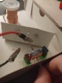
Electrons are attracted to the positive pole of a magnet. By spinning my rotator, my free electrons should alternate between being repelled and attracted, thus moving electrons creating a current. Unfortunately this is not working. All copper cables are connected to the axis of rotation, but my Volt-Meter is not detecting anything. I am sorry for this messy picture, I wanted to build a prototype first, in case something is not working. As it is right now. Lucky me...
 

Attachments

Tonyr1084

Joined Sep 24, 2015
7,894
Thrm; welcome to AAC.

May I ask how old you are?

How much do you know about electricity? Do you understand how a motor works? If so then you should also understand how a DC generator works. A DC generator is just a motor being spun by some external force. If it's not spinning it's not generating a voltage.
 

MrChips

Joined Oct 2, 2009
30,794
There are a number of reasons why your experiment does not work.

Let us begin with the first obvious one.

1) Did you wind the armature yourself? What kind of copper wire are you using? Is the wire bare copper or does it have an insulating coating of enamel?
 

Alec_t

Joined Sep 17, 2013
14,312
All copper cables are connected to the axis of rotation
It sounds as though you have created a short-circuit. If all wires are at the same potential there is no voltage (potential difference) for your meter to measure.
my Volt-Meter is not detecting anything
Is your meter set to read AC voltage? Your generator apparently has no commutator or rectifier so can't provide DC voltage.
 

Thread Starter

Thrm

Joined Dec 31, 2021
24
Thrm; welcome to AAC.

May I ask how old you are?

How much do you know about electricity? Do you understand how a motor works? If so then you should also understand how a DC generator works. A DC generator is just a motor being spun by some external force. If it's not spinning it's not generating a voltage.
Hi, thank you for your fast response, I really appreciate it! I am 20 years old by the way. I do know some things but just in theory. I could tell you about electric charge, electric potential, electric field, electric current, resistance and ohm's law. This is about it and I have heard about some other things but no deep understanding. I am sorry I didn't make it clear, I was spinning it but I just took a picture of the "generator"
 

Thread Starter

Thrm

Joined Dec 31, 2021
24
It sounds as though you have created a short-circuit. If all wires are at the same potential there is no voltage (potential difference) for your meter to measure.

Is your meter set to read AC voltage? Your generator apparently has no commutator or rectifier so can't provide DC voltage.
Another response, I am really grateful! I was wondering about the potential difference but I thought moving electrons by spinning between two magnetic poles would create a charge, maybe there is my mistake? No my volt-meter is detecting DC. I will get more information about commutators and rectifiers and how to build them but building them from scratch with barely nothing at home is not easy. Thank you though!
 

Thread Starter

Thrm

Joined Dec 31, 2021
24
There are a number of reasons why your experiment does not work.

Let us begin with the first obvious one.

1) Did you wind the armature yourself? What kind of copper wire are you using? Is the wire bare copper or does it have an insulating coating of enamel?
Hi, many thanks for your time! Yes I did everything myself and the copper is pure, I even tested it and it is conducting
 

MrChips

Joined Oct 2, 2009
30,794
Hi, many thanks for your time! Yes I did everything myself and the copper is pure, I even tested it and it is conducting
You cannot use pure, bare copper wire for this experiment.
When you wind a coil with wire the wire must have an insulating coating otherwise each turn of the wire will create a short circuit with adjacent turns of wire.

Magnet wire is pure, bare copper wire with a layer of enamel to create an insulating coating.

Now there other reasons why your experiment does not work. Want to hear more?
 

Thread Starter

Thrm

Joined Dec 31, 2021
24
You cannot use pure, bare copper wire for this experiment.
When you wind a coil with wire the wire must have an insulating coating otherwise each turn of the wire will create a short circuit with adjacent turns of wire.

Magnet wire is pure, bare copper wire with a layer of enamel to create an insulating coating.

Now there other reasons why your experiment does not work. Want to hear more?
Ah okay I will get more information regarding copper cables, thank you for this clue! I would love to hear more about my mistakes, I need to learn :) For your understanding, I am an trainee in a bank, unfortunately I am not very interested in this topic, so in my free time I am doing an online course about physics which really interest me. At the moment I am working on electricity but just in a book and on the physic-point of view. I would love to go further into engineering but I don't know where to start so I am not doing any rookie mistakes. Would you recommend any books or Youtube Channels, so I could enhance my skills/knowledge regarding engineering? I am sorry for my life story :) Thank you again for taking your time, I really appreciate it!
 

Thread Starter

Thrm

Joined Dec 31, 2021
24
Other than uninsulated wire, the most obvious(to me) is that of your magnets. Unless they are a one off type that has the poles on the long sides instead of the ends. Most flat bar magnets the poles are oriented at the ends not the middle. Look at this link to see what I'm talking about - http://hyperphysics.phy-astr.gsu.edu/hbase/magnetic/elemag.html
Cable it is... I will check on that, thank you very much. Actually the magnets are oriented at the middle, but thank you for pointing this out
 

shortbus

Joined Sep 30, 2009
10,045
I'll point out another thing. Having three coils will make your "generator" in reality an "alternator". A generator make DC and the alternator makes AC. Generators have an even number of coils, and alternator have uneven number of coils.

So if you make changes in your experiment using this rotor check on the AC scale of your meter.
 

MrChips

Joined Oct 2, 2009
30,794
There are many educational resources on physics and electricity on the internet.

Why not try AAC's own online educational tutorials. Click on the EDUCATION button at the top of this page.

You can also try the HyperPhysics site.
 

Thread Starter

Thrm

Joined Dec 31, 2021
24
There are many educational resources on physics and electricity on the internet.

Why not try AAC's own online educational tutorials. Click on the EDUCATION button at the top of this page.

You can also try the HyperPhysics site.
Oh, exciting :) I will do so! I was probably a bit overzealous, I should take my time and have a deep understanding, great answer, thanks so far
 

MrChips

Joined Oct 2, 2009
30,794
Now about the next problem.

Your magnets are stationary. That's ok.
The armature is the coil of wire wound around a soft iron core. This is called the rotor. This has to spin around the fixed magnetic field. There is no way to connect to the coil without getting the loose ends of the wire all wrap up around the axle of the rotor.

The way this is done on a real motor or generator is with the use of two slip rings or one split ring and a pair of carbon brushes.

1640966192771.png


SLIP RING

1640966036476.png


SPLIT RING
1640966118931.png

Stay tuned. There is still more to come!
 

Thread Starter

Thrm

Joined Dec 31, 2021
24
I'll point out another thing. Having three coils will make your "generator" in reality an "alternator". A generator make DC and the alternator makes AC. Generators have an even number of coils, and alternator have uneven number of coils.

So if you make changes in your experiment using this rotor check on the AC scale of your meter.
Oh, I can see what I did wrong, my experiment is build for AC and in order for it to work I need to add some components, thank you for your help
 

shortbus

Joined Sep 30, 2009
10,045
Another hint. The alternator is easier in the you only need two "slip rings" to get the power out of the rotor. A generator need a segmented "commutator". The slip rings need to be insulated from the shaft. One end of each rotor coil gets soldered to each slip ring and the other ends to the other ring. The coils on the rotor arms also need to be wound in the same direction, clockwise or counter clock wise doesn't matter, as long as they are the same. The same thing applies to connecting to the slip ring, the start of each coil needs to be connected to the same ring, again it doesn't matter which ring s long as they are consistent. The reason for this is called the "phase" of the wiring. An out of phase coil will cancel the other out one and give no output.

I put the quotation marks on words for you to Google, to see what I'm talking about, to help with you understanding why it matters in this.
 

Tonyr1084

Joined Sep 24, 2015
7,894
Was just about to suggest that myself. Stationary coils and rotating magnet(s). But this will produce AC, not DC. After producing AC you would have to rectify the current to get pulsating DC voltages. A cheap meter will have a hard time measuring the voltage because during AC generation your voltages will swing fully from positive to negative to positive to negative - ongoing like that.

If you're looking to build a generator simply for learning how to make such a device, a bar type magnet with a hole in the middle, a shaft and a drill to spin the magnet. A single coil will work but two will work better. And if you've ever seen old time photographs of hydro-electric dam generators you'll see a large number of coils about the rotating magnet. That is IF they use a magnet in those old generators
 
Top