Need help with a motor

Thread Starter

Alchemy One

Joined Oct 5, 2019
217
Hello.
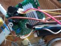
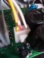
I like to be able to run this motor by some means. My first thought was perhaps using Arduino or perhaps possibly just supplying some voltage to its PWM pins which is a 4 pin hook up. Blue, white, black and green/brown ( color blind that I am).
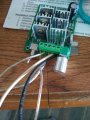
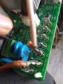
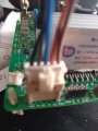
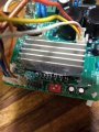
The motor seem to be a 220V + as power in on its power supply board. On the supply board there is hook up for three power wires to the motor (u,v,w) and 5 wires ( 3 hall and power in and ground). And then the PWM plug. See pictures.
I am curios why would I need pulse and that would need a control such as Arduino and codes to control the speed if I just want to run the motor.
Would I need to supply any power to the tach wire which I assume to be the white wire. ( Blue wire PWM) and the black, ground and the green power ( 5 volts?). Furthermore do I supply up to 12 volts to blue pwm wire, what about the tach (white wire)?
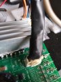
The plug with the black tape sticking out in the middle of the board is the PWM.
So I would think that needs supply coming in to along with the main supply of course. The other two goes to the motor, the hall and the 3 wires plug to the three terminals of the motor.
I am assuming this to be an induction motor and the purpose of the hall and pwm is to control speed and if not direction. This motor I would think is not operating on the principle of Hall censored, plus pwm, BLDC motor.
Oh by the way this was just one of the motor the ran a fan of a window air conditioning/heating unit.

One more last thing: Shouldn't I be able to run this motor using another bigger one that is BLDC as generator, hook up its three wires to this? Why not?
Any ideas?
Thank you.
 

Attachments

Last edited:

MaxHeadRoom

Joined Jul 18, 2013
28,688
For one, it does not appear to be an induction motor but a PM BLDC, complete with hall sensors.
A way to confirm is to short the 3 UVW and try to spin the rotor to detect resistance, if any, then it is a BLDC. or ECM.
There appears to be some sort of controller already
Max.
 

Thread Starter

Alchemy One

Joined Oct 5, 2019
217
For one, it does not appear to be an induction motor but a PM BLDC, complete with hall sensors.
A way to confirm is to short the 3 UVW and try to spin the rotor to detect resistance, if any, then it is a BLDC. or ECM.
There appears to be some sort of controller already
Max.
Right you are. You hit it on the head. So the power supply is a converter AC to DC and then supplies the motor with whatever DC based on speed, load and such.
Okay perfect.
I have a feeling that I can not get it going with a simple sensorless BLDC controller but maybe one that has hall sensor circuit as well. and I would think the motor need more than 5 or 10 volts. Let me check the resistance on the three wires. Okay they are about 100 ohms which is typical of 220 volt coils in my experience.
So what do I supply the PWM, that you see in the picture besides supplying it with AC?
Would that get it going as I assume it is what turns on the switch to DC part of the circuit that feeds the motor.
I have ran the motor with direct 120 V but I it is a little lame, and with some help with me jerking it and turning the magnet rotor. :) But let me think I don't think I was able to run it with this bldc supply, I should attach a picture of it here. This would mean that the motor needs at least 50- to 60 volts DC if not more.
Okay here two pictures, One that fed the motor and the auxiliary one I use sometime to run smaller motors here and there like Hard drive motor and the like things.
That little auxiliary one that can handle up to actually quite a bit volts was not able to run due to my power supply that goes up to 30 volts and 10 amps. plus it has no halls sensor.
 

Attachments

MaxHeadRoom

Joined Jul 18, 2013
28,688
You can either construct a microprocessor PWM controller or obtain a BLDC controller Off ebay, there is some nice BLDC servo amp types on ebay made by A-M-C etc.
Although it appears you have some kind of controller there?
Max.
 

Thread Starter

Alchemy One

Joined Oct 5, 2019
217
Yea, that is the controller and power supply. That is my point. That is what that is.
So what I am really asking if my mental picture conclusion has some sense in me saying that I just have to supply power to the pwm pins directly. You know you see it the harness with the black tape, I had to solder couple of wires since it was since two of them were cut hence the tape.
So would you know anything about the pwm as my understanding is it is nothing but means of control of power supply the same as voltage regulator or potentiameter... it's function is in that family so to speak.
That is one thing and another is the tach wire would need power besides PWM? there are 3 pin and 4 pin PWMs.. the only difference to my knowledge is that the 4 pin has an extra wire for tach.
There is also, if you look very closely in that controller a physical switch too that controls speed, it has 4 setting, using two switches. The two switches are on the right side of the heat sink ( you can see two square white looking things, that is the two switches) each switch says 1 and 2. depending where you move each switch, total combined gives you 4 different speeds. From 1400 to 1000 RPM. it is written on the board as well right adjacent to the hook up by the power supply side. There are 4 male things ( you can see them in the bottom left side of the picture not very clear but you can see them) that are sticking up along with the three that gets hooked to 220 power in.
 
Last edited:

MaxHeadRoom

Joined Jul 18, 2013
28,688
You typically have a BLDC controller which by way of the hall sensors commutates the required winding(s).
The command signal to operate the controller can be several methods, from a PWM command to a 0-10v DC version.
It all depends on the controller, the commutation for BLDC however is fairly standard, only two windings energized at any one time, .
Normally a tach is not involved in the process, unless there is some external need for it, Indicator etc.
Max..
 

Thread Starter

Alchemy One

Joined Oct 5, 2019
217
You typically have a BLDC controller which by way of the hall sensors commutates the required winding(s).
The command signal to operate the controller can be several methods, from a PWM command to a 0-10v DC version.
It all depends on the controller, the commutation for BLDC however is fairly standard, only two windings energized at any one time, .
Normally a tach is not involved in the process, unless there is some external need for it, Indicator etc.
Max..
I also thought of that. I didn't think I would need to supply that white wire (for tach), typically they are yellow in most 4 pin pwm I have noticed. So I just supply the blue wire pwm. I would think there won't be any explosion such a thermonuclear reaction... I just didn't feel there is any need to buy anything. I am just messing around. Plus I have hoarded so many motors and circuit boards.... somebody should really stop me. I have no room for my car now in my garage that is.
 

MaxHeadRoom

Joined Jul 18, 2013
28,688
The only thing puzzling in the controller in the link is how are the hall sensors powered?
They can vary a bit on power needs?
I would want to see the hook up documentation.
Max.
 

Thread Starter

Alchemy One

Joined Oct 5, 2019
217
The hall sensors are powered right from where it plugs in the slot it snaps into on the controller board. All together. 3 hall and a power and a ground. It is all one plug, one shot deal just like the three wires that supplies the motor in another plug. You can see them in the picture.
 

Thread Starter

Alchemy One

Joined Oct 5, 2019
217
The only thing puzzling in the controller in the link is how are the hall sensors powered?
They can vary a bit on power needs?
I would want to see the hook up documentation.
Max.
Check out these pictures, close shots. Everything.
The 5 wires to hall, the 3 wires to motor, the 4 wire for the pwm. You can also see the ac power supply and the 4 male plugs sticking up by the power supply. I think those 4 separate male for speed must have gone to the user interface along with pwm and the pwm fed one of those plugs that the user chose. As in clicking different settings with clicking of the knob on the face of the unit itself.
I have looked everywhere for schematics in my pile of electronics. Nothing yet. I also like to run one of them LG bldc hub motors. They are pretty impressive looking thing if you have seen them.
I also just posted another question. Optocoupler wiring,
 

Attachments

Top