Need help with 555 circuit

Thread Starter

nabs

Joined Oct 8, 2008
2
Hey guys,

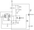
my group and I are currently working on a project, and we have to come up with an astable 555 circuit with variable duty cycle(10%-50%) to power a laser diode.

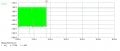
From the attached waveform, the pulsing suddenly stops after about 17 seconds, and it is rather noisy. Also, we need to bump the voltage up to 1.9V to 2.2V.

Would appreciate any help to correct these problems. :)
 

Attachments

Last edited:

mik3

Joined Feb 4, 2008
4,843
With your circuit you dont varu the pulse width but the output frequency of the 555. Here is a circuit for PWM by using a 555:

http://www.dprg.org/tutorials/2005-11a/index.html

Also, your led driver (transistor) is not connected properly. Its better to use a common emitter configuration to drive the led and even better an emitter follower (which will produce a fixed current through the led each time it is pulsed) but first give us the specifications of the led (voltage, current) and the part number of the transistor to tell you proper values of resistors.
 

neon9

Joined Oct 8, 2008
15
why the transistor don't need IT that put a res. in series from the out pin3 to the led. LM555 IS GOOD ~300MA. then ra to pin 7,6 +cap > to gnd. then use pin 2 to vary your pulse width. good luck.
 

Thread Starter

nabs

Joined Oct 8, 2008
2
With your circuit you dont varu the pulse width but the output frequency of the 555. Here is a circuit for PWM by using a 555:

http://www.dprg.org/tutorials/2005-11a/index.html

Also, your led driver (transistor) is not connected properly. Its better to use a common emitter configuration to drive the led and even better an emitter follower (which will produce a fixed current through the led each time it is pulsed) but first give us the specifications of the led (voltage, current) and the part number of the transistor to tell you proper values of resistors.

The specifications of the laser diode we're using are 2.2V, 270mA, 200mW, so we're trying to vary the intensity of the beam. The transistor is MPS2222A.

Also, what do you mean by "common emitter configuration" and "emitter follower"? :$
 
Last edited:

mik3

Joined Feb 4, 2008
4,843
Well, PWM wont work to control the illumination intensity of the Led's unless you use complicated circuits. I recommend you to use this circuit here:

http://www.allaboutcircuits.com/vol_3/chpt_8/7.html

It will provide a voltage controlled current source. By driving your led with constant current your illumination intensity will be constant independent of the voltage drop across the led which varies a little.
 

Audioguru

Joined Dec 20, 2007
11,248
Well, PWM wont work to control the illumination intensity of the Led's unless you use complicated circuits.
No.
Cars use a simple PWM circuit for changing the brightness of LED tail-lights for braking.
My Ultra-bright LED Chaser projects use a simple PWM circuit (a single Schmitt-trigger inverter variable pulse width oscillator) to vary the brightness of the LEDs from zero to full brightness. Here is my simple circuit:
 

Attachments

mik3

Joined Feb 4, 2008
4,843
If you just use the led for illumination your brain just take the average of the pulsing light and you see that the illumination varies. if you will use the led as to excite a phototranistor then you need to put some low pass filters in your circuit to get the average of the pulsing.
 
Top