Need help wiring digital motor starter in place of centrifugal starter switch on single phase motor

Thread Starter

Will Norris

Joined Nov 6, 2018
10
Hello I am trying to repair a motor on my craftsman air compressor. The centrifugal switch that switches between the start and run windings has broken and there are no parts available for the motor itself.
I found a few products that may bypass/repair the problem
1 http://store.eurtonelectric.com/univeralmotorstartmoduleupto3hp-3-1.aspx
and
2 http://store.eurtonelectric.com/univeralmotorstartmoduleupto3hp.aspx
The specs seem to meet my needs and the product seems to be for exactly what I need. But I need some help with wiring one of these into the motor circuit.
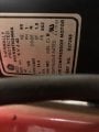
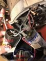
Now onto the motor it is a GE motor 2hp I will include the spec plate pic and a pic of the wiring accessible near the broken starter switch.
If anyone could help me figure out where one of these starters would connect into this motor I would really appreciate it.
Thanks
Will
 

Attachments

MaxHeadRoom

Joined Jul 18, 2013
28,576
Google 'potential relay start capacitor wiring diagram'
It should cover it for you.
But if the switch has failed open, the start winding is open circuit, so you may have to open the motor and short the connections of the centrifugal switch.
Max.
 

Thread Starter

Will Norris

Joined Nov 6, 2018
10
Max sir you have far overestimated my abilities. I did look up what you recommended and did learn a bit but I still don't feel confident I can safely and successfully pull this off yet. But I can tell you what I did learn.
On the rear of my motor there are three wires coming out Red, Black and Brown. Because I can find no schematic for my motor I have no idea what each one is. But if what i found is correct measuring the ohms through each leg should identify them.
According to the readings Black is my Common, Red is my start winding and brown is my run winding.
But I still don't understand how to hook the relay in. Does it replace the capacitors or is it in addition to?
i will reference the schematics of the 2 relays I hope to use.
120v3pin.jpg 120v4pin.jpg have found and hopefully someone can help me through the wiring process.
 

Thread Starter

Will Norris

Joined Nov 6, 2018
10
Also the motor is 120v and it has what looks like 2 power wires that come in from the side and disappear into the coils. As for the centrifugal switch it is external and can be seen in the pic above, I have it outlined. It loos like it only has 2 wires in, would that mean it is a spst switch and if so would a continuity test across it help in any way?
Thanks.
 

Thread Starter

Will Norris

Joined Nov 6, 2018
10
Here is a drawing of the motor, not exactly a schematic but how it appears just by looking at it , if someone could help draw one of the schematics from either of the two relays listed above into this I think it may be mission accomplished. I drew out how I concluded as to what the motor coil wires "as I believe them to be" are. But I could be wrong and someone with more knowledge may be able to correct any mistakes by looking at what the motor drawing/pic shows. Based on my measurements the black wire is common, the red is start winding and the brown is the run winding.
motor schematic.jpg
 

Thread Starter

Will Norris

Joined Nov 6, 2018
10
Ok I have added to the schematic what I believe is the correct wiring of the 4 wire isovolt unit #2 shown above.
If someone who has more experience with this than I do could look over my crude diagram and leave input I would be very thankful. Also in this configuration would I be able to remove the centrifugal switch all together?
Thanks
motor wiring final.jpg
 

MaxHeadRoom

Joined Jul 18, 2013
28,576
3.4 ohms is the total of the two windings, it does not have three as you have shown, the high value one is the start winding which requires the start switch.
Also, if the switch is external it is not a centrifugal switch, this would be mounted at the motor shaft.
Did the original use an external start switch?
It is late, I will look it over tomorrow.
Max.
 

Thread Starter

Will Norris

Joined Nov 6, 2018
10
Thanks Max,
the centrifugal switch is internal to the motor as you stated but is easily accessible as it is mounted to the rear of the motor under a plastic cover, my second picture in the first post shows the switch location circled in blue. The cover has flimsy plastic mounting points that broke in tern the centrifugal start switch lever was broken, that part is not available. That's why I'm looking for another way to start this motor.
 

MaxHeadRoom

Joined Jul 18, 2013
28,576
Remove the 3.5Ω winding from your DWG. the 2.2Ω is your start winding and the 1.2Ω is the run winding.
The simple drawing like this should get you going.
N.C. PR contact wired across existing motor switch, ensure it has failed in the open position.
Max.

upload_2018-11-7_9-10-21.jpeg
 
Last edited:

Thread Starter

Will Norris

Joined Nov 6, 2018
10
So on your upper diagram does the number 5 location hook to the center common tap? Or does it connect to a L2? Is L2 and common tap on the motor the same location?
 

MaxHeadRoom

Joined Jul 18, 2013
28,576
PR 5 would connect to the common (C) or L2 in fig (a), IOW 2 & 5 goes across the Red/Blk and PR replaces the N/C start SW.
PR2 would connect to the Start winding N/C junction
PR1 to the start Cap is in series with this combo.
Max.
 

Thread Starter

Will Norris

Joined Nov 6, 2018
10
Max I thank you for your effort and time, but I still can't wrap my head around this.
I understand your diagram clearly but it doesn't resemble the circuit I have.
The second picture in my 1st post shows the wiring arrangement and I have ohmed them out. Can you help me by looking at that pic and describing how the relay fits my circuit? Black wire = Common
Red wire = Start
Brown = Run
 

MaxHeadRoom

Joined Jul 18, 2013
28,576
If you take the upper left DMS03u DWG and substitute in your components, they show two run winding's but yours is represented by the Red to Blk (LR) , the start winding is Brown to Blk (LS). Ignore the other run winding shown.
The single start capacitor is CS and the Run cap CR.
As you see the common end of the run & start winding is common to each other and connected to Neut (Blk)
The DMS L and C is your new N/C start switch.
See if this works for you! ;)
Max.
 

Thread Starter

Will Norris

Joined Nov 6, 2018
10
Ok I see what your saying but is it the other way around?
The Brown to Black on my motor has a lower resistance would it not be the (LR) Run winding?
And the Red to Black has a higher resistance would it be the (LS) Start Winding?
But I understand L and C will replace the failed switch Would A then run to the red wire at the top of the CR and would N also connect to N above the CS?
 

MaxHeadRoom

Joined Jul 18, 2013
28,576
Yes it should be the opposite run and start winding. brown-black = run etc.
Red wire to A and CS and CR.
N only has the run and start winding common connection if wired using the DMS connection DWG.
Just substitute the connections as shown for your motor .
It is a different config, to the unit in post #9.
Max.
 
Top