Facebook
 Google
 GitHub
 Linkedin
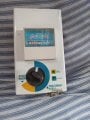
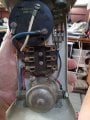
I have built a replacement timer for an Lectra San marine toilet system.
Component list:
H3Y 3 minute delay timer
12 volt 3 or 4 post 100+ amp starter type solenoid (continuance duty..gets hot)
12 volt 30 amp automotive relay (4 post)
one SPDT toggle switch
one momentary button switch
a fuse bank for 4 fuses or 4 separate fuse holders.
wire and connectors
The solenoid is importand in this application as when timer shuts off the activating auto relay then the system has no power until re triggered by triggering the solenoid again using the momentary switch to the solenoid directly.
The timer is powered on once the solenoid is triggered. The timer has activated the auto relay. The timer shuts off the power after 3 minutes to the relay and the auto relay shuts off power to solenoid. Whole system has power off until re triggered.
The SPDT toggle is for the mixing motor. In postion A it powers the motor independently while bowl is being cleared manually.
Once cleared move switch to position B then press the momentary switch and all motors and electrode will operate for 3 minutes and all units shut down until re triggered.
So...What connects where?
The negative wire solenoid ground to #86 on auto relay and #13 on timer.
The positive wire from solenoid out terminal to #1 and #14 on timer
The auto relay... #30 to #1 on timer. Also #85 to #9 on timer. Also #87 to solenoid "S" (trigger).
SPST switch. Common goes to mixing motor . A to always hot. B to solenoid out. Install fuses for motors and power out to timer #1
Momentary switch...you can figure it out.
Solenoids get hot. A 3 minute cycle should not be repeated until a cool down of a few minutes.