Need help understanding timer circuit?

Thread Starter

UsernameMD

Joined Sep 12, 2014
12
Hi,

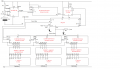
As the title suggests I need help understanding the timer circuit in the schematic attached.

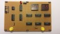
I built this project in college last semester, but did not design it.

It is a circuit designed to measure a users reaction time to an event.

The user presses the set button and after some delay the LEDs start displaying the count. The object is to stop the count as quick as possible so as to measure the users reaction time. The LEDs are then reset by pressing the reset button, and the LEDS will go to '000'

Just wondering how this works, Digital is not a strong point of mine, and I am trying to change that.

Thanks
 

Attachments

shteii01

Joined Feb 19, 2010
4,644
555 provides the clock signal.

Frequency of 1 Hz.
1 Hz=1/Time
Time=1/1 Hz
Time=1 second
So the counter counts at 1 second interval. You start at 0, after 1 second that count is changed to 1, after one second the count is changed to 2, after one second the count is changed to 3, and so on.
 

Thread Starter

UsernameMD

Joined Sep 12, 2014
12
555 provides the clock signal.

Frequency of 1 Hz.
1 Hz=1/Time
Time=1/1 Hz
Time=1 second
So the counter counts at 1 second interval. You start at 0, after 1 second that count is changed to 1, after one second the count is changed to 2, after one second the count is changed to 3, and so on.
Sorry I should have been more specific, I am very weak at Digital and trying to improve. Here is a picture of the 555 area of the board.

Why are there two resistors and a capacitor there?

Also does this mean the 555 is in astable operation (I am just comparing with the datasheet now)? If so what exactly does astable mean?

Thanks so much for your help, I apologise for the silly questions.
 

Attachments

shteii01

Joined Feb 19, 2010
4,644
Two resistors and one capacitor are used to determine the time period. This way you the user say: I want square wave with 2 second period, 50% duty cycle (1 second high, 1 second low). So you pick a capacitor, you pick one resistor, solve the equations to find the second resistor. Build the circuit. Done. Here is 555 calculator and a little explanation:
http://www.csgnetwork.com/ne555timer2calc.html

The datasheet should have all the relevant info, including sample circuits of 555, including explanations.
 

Dodgydave

Joined Jun 22, 2012
11,304
Looks like you missed off the 1khz clock,for the reaction time, the 555 provides a 1 second enable pulse to set the reaction timer going,as soon as the person stops the timer,the counter will display it in milliseconds (1000)= second.
 

Thread Starter

UsernameMD

Joined Sep 12, 2014
12
Looks like you missed off the 1khz clock,for the reaction time, the 555 provides a 1 second enable pulse to set the reaction timer going,as soon as the person stops the timer,the counter will display it in milliseconds (1000)= second.

The 1kHz clock was supplied by frequency generator in the lab. I don't understand when you say I 'missed off' the 1kHz clock?
 
Top