Please look at the attached image, For part B) i) Why did he calculate the Rt as if it were in a parallel circuit? Should the answer not be 4mF + 6mF = 10mF? Im confused.
Please look at the attached image, For part B) i) Why did he calculate the Rt as if it were in a parallel circuit? Should the answer not be 4mF + 6mF = 10mF? Im confused.
He didn't calculate Rt (the total resistance). He calculated Ct (the total capacitance).
The question is trying to see if you understand what capacitance is and how capacitors behave when connected in series. Clearly you don't. But that's fine. You are at the stage of learning this stuff so you are not expected to have it down. But do not just settle for a "capacitors in series act like resistors in parallel" explanation -- capacitors in series do NOT act like resistors in parallel -- capacitors do not act like resistors, period. While the form of the equation for combining capacitors in series is the same as the form of the equation for combining the resistors in parallel, that is purely by coincidence. What YOU should be able to do is quickly and confidently DERIVE the equation for combining them in either series or parallel based on your understanding of Kirchhoff's Laws and the definition of capacitance.
Capacitance: The capacitance (of a linear capacitor) is defined as the ratio of the charge separation and the voltage created by that charge separation.
C = Q / V
If you have two (initially uncharged) capacitors, C1 and C2, in series and a single (initially uncharged) capacitor, Ct, on the right that have the same effective capacitance, then if you push the same amount of charge, Qt, into both circuits you will get the same total voltage, Vt, across each circuit.
For the left circuit, the total voltage is the sum of the voltages across each individual capacitor (Kirchhoff's Voltage Law), so
Vt = V1 + V2
and the charge on each capacitor is the same and is equal to the total charge put into the circuit as a whole (Kirchhoff's Current Law), so
Qt = Q1 = Q2
Since V = Q / C, we can rewrite the voltage equation as
Vt = (Q1/C1) + (Q2/C2)
and, in light of the charge equation, we can write it as
Vt = (Qt/C1) + (Qt/C2) = Qt[(1/C1) + (1/C2)]
For the right hand circuit (the single capacitor), we simply have
Vt = Qt / Ct
Equating the two, we have
Qt / Ct = Qt[(1/C1) + (1/C2)]
Dividing both sides by Qt we get the formula for how to combine capacitors in series
Think about it.
Impedances in series increase the total impedance and impedances in parallel reduce the total.
Since a larger capacitance has a lower impedance, then two capacitors in parallel must have a lower equivalent capacitance than either one alone.
Thus series capacitors can't be directly added.
On the other hand, the impedance of resistors and inductors both increase with their value, so there values add together when in series.
The problems are at a level commensurate with just starting out with capacitors. He very likely has yet to even learn about an inductor and the very term "impedance", in any form, is likely still well over the horizon.
I truly appreciate you guys helping me gain a better understanding, I understand the relationship between capacitance and equivalent capacitance a bit better now. Thank you for explaining that everyone. And I realize that reactance is a phase difference between current/voltage, in inductance the voltage leads current by 90, and vise versa for capacitance reactance. And with resistance there is no phase difference, just magnitude.
I got an exam coming up in 4 days, its for stationary (power engineering), it's a written exam on refrigeration, thermo, electricity and lots of theory. I have quite a few pages of someones note and I'm understanding the vast majority of it. Just a few things I have been stuck on. I have been googling, watching youtube videos etc. I wish I had an electrician friend to help me out, but no one has time so I'm alone on this.
I just have one more question, which is understand phasor diagrams and how to draw them. I googled etc, but still a little confused.
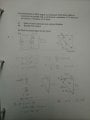
I'm trying to draw the phasor diagram in question, instead of a new thread I thought i'd add to this. Please have a look at the question with answers, and then my attempt at the phasor diagram. I don't have a good understanding of this. Thank you.
 Facebook
 Google
 GitHub
 Linkedin
 290.9 KB Views: 12