Need help understanding this wave form

Thread Starter

Tonyr1084

Joined Sep 24, 2015
9,744
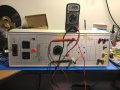
Just got this old power supply from a local school that was clearing their shelves of old equipment. Got several of these power supplies, an old Heath Kit Oscilloscope, and a bunch of other stuff. This power supply seems to be working normally. I get variable AC on the AC terminals (my drawing designated V1 & V2), and I get a clean variable DC on the DC terminals (my drawing designated V3 & V4).

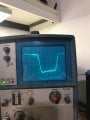
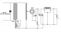
While scoping the outputs I noticed the AC wave form is not sinusoidal. Looking at the attached schematic, can you explain why this is?
 

Attachments

wayneh

Joined Sep 9, 2010
18,104
Do you see the same result with a load attached?

Also, is it possible the sine wave is being clipped (by a zener for instance) to protect your scope?
 

Thread Starter

Tonyr1084

Joined Sep 24, 2015
9,744
Do you see the same result with a load attached?
The system has a load resistor built in. It's 1500 Ω. When the DC is turned all the way up I see 135 volts. The resistor is 20 watts.

Also, is it possible the sine wave is being clipped (by a zener for instance) to protect your scope?
I've not seen this before with this scope. As the meter is displaying, I was running the system at 20 VAC. Scope was showing a 20 volt peak wave, albeit not a nice looking sine wave. I don't think the scope was modifying the signal. I had it set to AC; 10 volts per division, so the wave was 40 V PP.

I wouldn't say the scope is exactly calibrated, but I do believe it's within a few hundredths of a volt. Even if it were off by 0.1 volt, it's still looking like a pretty fair representation of the wave form in shape and magnitude. When I varied the voltage the wave changed in amplitude but did not alter its shape. So I was just wondering why it was doing that. Maybe it's that really big capacitor on the tiny secondary of the main transformer causing it - I don't know. That's why I'm asking. Maybe that cap is bad. Didn't LOOK bad when I had it open. But I really don't have any way of testing a cap that big. (dimensionally approximately 4 inches high by about 2 1/4 inches wide by about 1 1/2 inches thick. Rounded sides) I should have taken pictures when I had it opened.

When I opened it I found some potentially hazardous situations. A loose mains line, a badly soldered ground - a plug with the ground probe broken off. Neutral was a wire soldered to a lug terminal, crimped and wrapped in white cloth tape. Real hack jobs. I fixed those issues but the wave form is still the same.
 
Last edited:

crutschow

Joined Mar 14, 2008
38,507
I think I have solved the puzzle.
See that extra secondary winding and capacitor at the bottom?
That appears to be part of an older design ferroresonant constant voltage transformer.
The capacitor and transformer inductance form a tuned circuit which resonates at the main's frequency.
This causes saturation of the transformer core and this saturation is largely independent of the input voltage.
The output voltage is thus also basically independent of the input voltage over a wide range of voltage.
This saturation is what generates the observed flattening of the peak output voltage waveform.
 

WBahn

Joined Mar 31, 2012
32,840
I think I have solved the puzzle.
See that extra secondary winding and capacitor at the bottom?
That appears to be part of an older design ferroresonant constant voltage transformer.
The capacitor and transformer inductance form a tuned circuit which resonates at the main's frequency.
This causes saturation of the transformer core and this saturation is largely independent of the input voltage.
The output voltage is thus also basically independent of the input voltage over a wide range of voltage.
This saturation is what generates the observed flattening of the peak output voltage waveform.
At first I wasn't too sure about this. Reading that reference implies that the constant voltage that is being referred to is not the instantaneous voltage, but the amplitude of the sinusoidal voltage. It does say that the older designs suffered harmonic distortion, but indicates that it was less than about 4%. It says that modern ones produce pure sinusoids (which I take to merely mean that the THD is below some threshold).

I found this reference: http://www.aelgroup.co.uk/faq/faq001.php

This also indicates that the intent it to produce a constant amplitude sine wave output largely independent of the shape and amplitude of the input waveform.

However, I also found this reference: https://coefs.uncc.edu/mnoras/files/2013/03/Transformer-and-Inductor-Design-Handbook_Chapter_11.pdf

It states explicitly that the output of a constant-voltage transformer is essentially a square wave, specifically noting that this is desirable for rectifier applications.
 

crutschow

Joined Mar 14, 2008
38,507
............
This also indicates that the intent it to produce a constant amplitude sine wave output largely independent of the shape and amplitude of the input waveform.

However, I also found this reference: https://coefs.uncc.edu/mnoras/files/2013/03/Transformer-and-Inductor-Design-Handbook_Chapter_11.pdf

It states explicitly that the output of a constant-voltage transformer is essentially a square wave, specifically noting that this is desirable for rectifier applications.
I noticed the different descriptions of the output waveform also.
Apparently it can be designed to have either type of output depending upon the output use.
I guess for Tony's circuit they designed it primarily with a square-wave to drive the bridge rectifier DC output.
It could give some odd results though to someone who is using the variable AC output into a load that is expecting a sinewave.
 
Top