 Facebook
 Google
 GitHub
 Linkedin
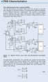
I am trying to troubleshoot a prebuilt 2-axis PSD circuitboard similar to this circuit http://www.osioptoelectronics.com/application-notes/AN-Position-Sensing-Photodiodes.pdf, last page on the left (see a simplified image below). We have a laser spot on the detector. (our circuit is similar to this one, not the one we are actually using).
If you are not familiar with these circuits then you might need to read the larger document. I'm going to assume that you do know how they work.
One of the critical functions of the circuit is to make the output signals that represent the spot position immune to the intensity of the spot. They do this by creating a third value that represent the intensity and dividing it into the X and Y axis signals (which also grow with light intensity).
How is that summing amp at the bottom supposed to work? At zero photodiode current the output will be the bias voltage on the photodiode (3V in my case). Then it goes down then below zero as the photocurrent goes up. This makes no sense to me so I must be dense about something here since it IS an accepted circuit.
Any help appreciated. thanks.
Attachments
-
 88.6 KB Views: 5


