Need help understanding schematics

Thread Starter

tomatotomatomy

Joined Dec 16, 2008
2
Hi all,

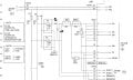
I'm trying to understand an electronic schematic to troubleshoot a machine, but the circuit is nothing I have ever seen before nor could I find on the internet.

r and t is supposed to be a 200Vac, goes through a rectifier and I'm supposed to get 90Vdc at BA1 and BB1.

I'm reading 280Vdc on my fluke mulitester.

I have no idea about the components in between the input and output.

Help? :confused:
 

Attachments

pwdixon

Joined Oct 11, 2012
488
280dc is just 200ac rectified ie 200x1.414.
If you know you should get 90V then something on the output side must be affecting BA1 or BB1, there's nothing in the circuit you have given that can be diagnosed to identify that. We would need more circuit to even guess at the problem. All that can be said is look further in the circuit after this circuit output for the problem.
 

MaxHeadRoom

Joined Jul 18, 2013
28,688

MaxHeadRoom

Joined Jul 18, 2013
28,688
The diagram is drawn rather poorly, it should have termination dots where a connection is made, when AC is rectified without capacitor smoothing you will not get x 1.414 but the input AC value or something a little less.
F5 and F6 are indicator fuses.
The black reverse diode items across the rectifiers are MOV's.
xx3 & xx4 are R/C snubbers.
Max.
 

pwdixon

Joined Oct 11, 2012
488
But XX3 looks like a filter and may well have capacitive properties, assuming the load is missing the output would smooth to the peak value perhaps then.
 

MaxHeadRoom

Joined Jul 18, 2013
28,688
I take the symbol for xx3 & xx4 for R/C snubbers which typically would be a ~200Ω in series with .15μf cap?
If so they would not retain any peak ripple at those values for even a least significant load.
Max.
 

pwdixon

Joined Oct 11, 2012
488
I take the symbol for xx3 & xx4 for R/C snubbers which typically would be a ~200Ω in series with .15μf cap?
If so they would not retain any peak ripple at those values for even a least significant load.
Max.
Why would the capacitor not hold the peak value under no load conditions? I would agree if the resistor was in parallel though.
 

MaxHeadRoom

Joined Jul 18, 2013
28,688
If zero load existed it would register some value above RMS, but with the existence of any small current it would register below RMS.
Max.
 

MaxHeadRoom

Joined Jul 18, 2013
28,688
The mean DC created will depend on the value of the snubber resistor/capacitor combo there will be a small current flow through the snubber at all times presenting a very small load.
Max.
 
Last edited:

pwdixon

Joined Oct 11, 2012
488
The mean DC created will depend on the value of the snubber resistor/capacitor combo there will be a small current flow through the snubber at all times presenting a very small load.
Max.
Is that an indication that the capacitor is not perfect and has leakage or is it something else?
 

pwdixon

Joined Oct 11, 2012
488
No, a capacitor has capacitive reactance in ohms, just as an inductor has inductive reactance, again in ohms, one of the dependendents is frequency.
http://www.sayedsaad.com/fundmental/16_CAPACITIVE REACTANCE .htm
Max.
But with a rectifier in front of the capacitance with no load wouldn't the capacitor just charge up to the peak voltage. In any case as originally posted the voltage measured appeared to be the peak so wouldn't that also tend to support the explanation. Otherwise how did the OP measure something that looked like the peak value?
 

Thread Starter

tomatotomatomy

Joined Dec 16, 2008
2
Hi all,

Thanks for helping out.

This is a Japanese machine, and I assume the drawing is not a proper one as to "not divulge too much information".

The 90Vdc output is used to power a servo motor's electromagnetic brake, maybe inductive coil or something similar?

What I don't understand is how do I measure the DC output with a multitester? Why am I getting 280Vdc? Am I using a wrong tester?

Just to add: I took the reading without load to the circuit
 
Last edited:

MaxHeadRoom

Joined Jul 18, 2013
28,688
This is a Japanese machine, and I assume the drawing is not a proper one as to "not divulge too much information".
The 90Vdc output is used to power a servo motor's electromagnetic brake, maybe inductive coil or something similar?
What I don't understand is how do I measure the DC output with a multitester? Why am I getting 280Vdc? Am I using a wrong tester?
Just to add: I took the reading without load to the circuit
What is the voltage when connected to the load?
BTW, one symptom of Fluke meters is when the battery runs low it can give all kinds of excessive voltage readings before you get the low battery indicator.
Max.
 

pwdixon

Joined Oct 11, 2012
488
Hi all,

Thanks for helping out.

This is a Japanese machine, and I assume the drawing is not a proper one as to "not divulge too much information".

The 90Vdc output is used to power a servo motor's electromagnetic brake, maybe inductive coil or something similar?

What I don't understand is how do I measure the DC output with a multitester? Why am I getting 280Vdc? Am I using a wrong tester?

Just to add: I took the reading without load to the circuit
So just to say again it's just root 2 times the rms value, and since you measured with no load there was no drop in the rectified value. Unless MaxHeadroom says I have it wrong again and has a better answer of course.
 
Top