Need help to pull to gound a 13vdc voltage via a 5vdc control voltage

MCU88

Joined Mar 12, 2015
358
Thanks for the reply's,
I'm not sure if I have completely explained what is happening.

I'll simplify,
I have a +5 voltage with a ground coming from an RCA jack. The center is + the outer is the - This is the control line,
It plugs into the line I want to control. (assuming I can figure out how to interface)
the controlled line has a +13 voltage and it's own ground (also RCA same as above) that needs to be grounded to turn on.
The +5 voltage grounds itself when I tell it to.(and goes back high again when told)
The device I need to control needs to be grounded to turn on and then go back high again when the +5 goes back high, in turn letting the 13 go back high and thus turning the device off.

Hopefully that makes some sense.
Hello....

Mike and myself have provided you with working solutions already. They are both similar using an opto coupler. Mike is a LOT older and even more experienced than myself, so I would go with his solution....
 

Thread Starter

JamesCO

Joined Mar 19, 2015
6
I believe that my posting (#16) does all you said...
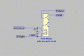
There is no PTT line. just two positive and negative leads, one set per side. control side 5vdc, controlling/switching 13vdc on and off.
your circuit looks nice but complicated. The way I understood I could use a spdt 5vdc relay to switch the 13 on and off.
 

MikeML

Joined Oct 2, 2009
5,444
There is no PTT line. just two positive and negative leads, one set per side. control side 5vdc, controlling/switching 13vdc on and off.
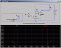
Then call it anything you like. Call it the "input to the box on right" in your drawing. I got the name "PTT"
Mike...

Still waiting on that transistor only solution... I'll pay you $10 PayPal if you can do it.
from your drawing.
your circuit looks nice but complicated. The way I understood I could use a spdt 5vdc relay to switch the 13 on and off.
If you understand how to do it with a relay, then why did you waste our time?

You are going to have to prove that the output from the "box on the left" can source enough current to actuate a relay coil. I'll take a bet that it wont.
 

MikeML

Joined Oct 2, 2009
5,444
Max,

If you read the OP's requirements very carefully, the implication is that he does not have access to either the +5V supply on the source side (only its oV end and the input signal), nor the +13V supply on the destination side (only its 0V end and the load).

He has not yet convinced us or himself that the 5V input signal is capable of driving a 5V relay coil (or the LED side of an opto-isolator). Unless he can, he will need access to the +5V supply terminal to source current to the relay coil or opto-isolator.
 

MaxHeadRoom

Joined Jul 18, 2013
30,772
As the source is a PC, then a solution to that would be to obtain the power from a USB port via a 2 wire source?
In his own admission he does not know exactly how to proceed, so he may be unaware that the +5 and the +13 v of the sequencer is required, although it may be available in some fashion he is unaware of.
Max.
 

Thread Starter

JamesCO

Joined Mar 19, 2015
6
Then call it anything you like. Call it the "input to the box on right" in your drawing. I got the name "PTT"


from your drawing.


If you understand how to do it with a relay, then why did you waste our time?

You are going to have to prove that the output from the "box on the left" can source enough current to actuate a relay coil. I'll take a bet that it wont.
If I knew how to wire it up I wouldn't have asked. (wasted your time)
As I said in my first post I'm a neophyte.
The box on the left has the current to actuate the relay. Again, This power does not come from a PC whatsoever.
I don't know how to wire up a 5vdc coil to do what I'd like.
Your fancy solutions look great but are greek to me. I'm not an electronics hobbyist and don't pretend to be one either. This is a means to an end, Once it's working I won't be screwing with it.
I may be at the point of sending it to someone to do it if I can't do it with a 5volt relay and need to use your schematic or similar.
I was/am asking for help on how to wire a Radio shack #275-0240 5vdc relay into my configuration to switch the +13 on/off
It thought it might be real simple but quickly went way over my head.

I don't have an interest in learning the hows and why's. (I may be in the wrong place)
This is a very small part of a much larger project and this is the last hiccup I need to overcome for the project to function.
If someone could help me by holding my hand and giving a quick step by step (+5 volt wire goes here, -13volt there, etc.) instruction I'd be enternally grateful.
If you can't do that or are unwilling to help in this manner, PM me the info for a good tech I can pay to have this sent to.
Thank you.
 
Connect +5V to one side of the relay coil and the +5V-0V control to the other. You should also connect a 1N4001 diode across the relay coil with the band to the +5V side of the relay coil.
Then, connect one side of the normally-open contact to 0V and the other to the 13V control line.

The relay solution assumes that your 5V-0V control signal can sink enough current to power the relay coil.
 
Last edited:

MaxHeadRoom

Joined Jul 18, 2013
30,772
If you can't do that or are unwilling to help in this manner, PM me the info for a good tech I can pay to have this sent to.
Thank you.
The biggest problem here is that so far there is so much guess work, in order to obtain a definite answer all the details have to be known of the PC end and the sequencer end.
I am afraid if you not able to supply these we are all spinning our wheels trying to decipher it, for general interface devices there is generally more to them than you have described, which so far is just a black box with in and out.
It is hard enough doing this from a distance without sufficient information.
Max.
 

Søren

Joined Sep 2, 2006
472
The way I understood I could use a spdt 5vdc relay to switch the 13 on and off.
A SPST reed relay would be quite enough and will require some 10mA..25mA depending on the selected coil resistance. If your 5V source can supply that, you only need the reed relay and a flyback diode to protect the source.

Regards,
Søren
 
Top