Need help to light up 8 LEDs with different color

Thread Starter

jenovauh

Joined Jul 4, 2013
246
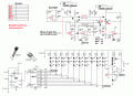
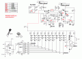
Here is what I think will work, do not know if or when I'll put it on a breadboard. Still missing is the boost, lots of chips and inf around or we scn roll ower own. Note that it is on full time except when battery is low or night. Really short on part #, mine are mostly surface mount, in an earlier post believe a suitable P-ch FET was listed, you have comparators, diodes ,plain 1N914 or equiv., shottky, 30V, 1A , V ref- LM 336Z, 2.5V. Variable resistors best if multi-turn. 9 V battery is to allow high drive for U5, good for shelf life a beyond. Looks like I had wrighters cramps & did not lable diodes- for another day. Maybe we'll get some help!!
Sure I do have the diode you mention but not the LM336Z 2.5v. No worry I will get that as well. And thank for the charging circuit, looks complicated to me, I hope I have no problem layout them out lol.
 

Thread Starter

jenovauh

Joined Jul 4, 2013
246
Here is one option: Each string runs at 750 CPS @ 10% duty, but the 555 clock is running @ 10 times 750. The string drivers can be just about any thing that you have 10 of. The average current drain is only about 25 mA, not much light. As an alternate , two strings can be connected to each of 5 drivers and clock halved, giving 20%. 4017 would be reset from pin 1 to give a circulating 5 count. The V regulator is just to keep LED operating V at or below 9V. When battery backup is added, tighter control will be needed. Part of IRLZ44N got lost.
I had attached the LED array circuit. Dont understand which 2 part are they.

1: Capacitor value?
2: Is that a 555 timer? And if it is, how many 555 timer are use in the circuit cause the other drawing have another 555 timer close to the 4017 counter.
 

Attachments

tracecom

Joined Apr 16, 2010
3,944
The capacitor is a .1μF ceramic, and the IC is an op-amp, but I haven't been following the thread closely, so I don't know which op-amp.
 

Bernard

Joined Aug 7, 2008
5,784
The triangle looking thing is a comparator, LM393.
Just one 555 & one 4017.
On Bt charger, pin # left off as not known which comparator would be used, LM393= 2 comparators or LM339 which has 4. Sometimes it is easier to to have fewer in a package to keep wires shorter & easier placement.
On Bt charger, as charging current is small [ C/25 ] only the constant current step is used untill Bt V reaches 8.3V, then SP-2 is disconnected by U6 & the setting of U4 is changed so re connection starts when Bt V falls to 7.3 V. Will add more inf as time permits.
Note that logic power comes from all sources & is available at arrow above C1. Keep questions coming.
No # 1k by Day-Night to be removed
 
Last edited:

Thread Starter

jenovauh

Joined Jul 4, 2013
246
The triangle looking thing is a comparator, LM393.
Just one 555 & one 4017.
On Bt charger, pin # left off as not known which comparator would be used, LM393= 2 comparators or LM339 which has 4. Sometimes it is easier to to have fewer in a package to keep wires shorter & easier placement.
On Bt charger, as charging current is small [ C/25 ] only the constant current step is used untill Bt V reaches 8.3V, then SP-2 is disconnected by U6 & the setting of U4 is changed so re connection starts when Bt V falls to 7.3 V. Will add more inf as time permits.
Note that logic power comes from all sources & is available at arrow above C1. Keep questions coming.
No # 1k by Day-Night to be removed
Sure thanks for the explanation, I will try to draw the whole circuit schematic together and let you see if anything is not correct. Before I start building it. :)
 

Thread Starter

jenovauh

Joined Jul 4, 2013
246
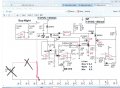
Finally finished drawing the schematic, sorry if I did not draw it correctly. It is my first time drawing that lol. Anyway after drawing them, I have some queries in the schematic which I do not understand and do not know exactly how to link them up to form a complete circuit. Below are the questions.

1. U1 = ?
2. U2 = ?
3. U3 = ?
4. U4 = ?
5. U5 = ?
6. U6 = ?
7. Boost = ?
8. BT = ?
9. 2.5V is for? and what does it do or how do I link it to the circuit?
10. R3, R9, R13 & VR1 are potentiometer right? And what do I adjust them for?
11. How to link the LED array and charging circuit together?
12. All the shottky diode symbol is using 1N914?
13. Lastly can you check and confirm my drawing is correct as what you had designed?
 

Attachments

Bernard

Joined Aug 7, 2008
5,784
Let's make all comparators LM393, need 2 1/2, U 1-4, I'll add pin #s.
U 5-6, FDS9435, SM, or NTE2371 TO220 package, or equivalent,; I soldered on leads to a FDS9435 to plug into BB.
Boost- not made yet
Bt = Li-ion battery
LM336Z, 2.5 V ref is used as a reference for all comparators, will add drawing in AM.
# 10 yes; instructions will follow.
# 11, see post 120, lower left, short form of LED ckt connects to C2+. When combined there are then 2 caps 100uF & 10uF,C2, 10 will drop & 100uF becomes C2
Diodes look fine, shottky have the wiggles, 1N914 straight cathode, or equiv. 1N4148, or another shottky is OK, then they are all the same.
Checked all of LED part, most of Bt. Nice drawing.
 

Thread Starter

jenovauh

Joined Jul 4, 2013
246
Let's make all comparators LM393, need 2 1/2, U 1-4, I'll add pin #s.
U 5-6, FDS9435, SM, or NTE2371 TO220 package, or equivalent,; I soldered on leads to a FDS9435 to plug into BB.
Boost- not made yet
Bt = Li-ion battery
LM336Z, 2.5 V ref is used as a reference for all comparators, will add drawing in AM.
# 10 yes; instructions will follow.
# 11, see post 120, lower left, short form of LED ckt connects to C2+. When combined there are then 2 caps 100uF & 10uF,C2, 10 will drop & 100uF becomes C2
Diodes look fine, shottky have the wiggles, 1N914 straight cathode, or equiv. 1N4148, or another shottky is OK, then they are all the same.
Checked all of LED part, most of Bt. Nice drawing.
Thanks again Benard. :) I am trying to draw the best I can as it is also your hard-work to help design and teaching me over here. And it can be shown to the rest to learn as well.

I had label the all the components in the drawing which you had given me the answer. I will be using 1N4148 for all the schottky diodes as I have quite a lot of them. I had also connect the LED array to charge circuit as per your instructions.

The Li-ion battery can be 2 X 3.7V in series right? Kindly double check the drawing when you are free. Still waiting for my 4017 to arrive lol. I had pretty much configure the rest of the circuit.
 

Attachments

tracecom

Joined Apr 16, 2010
3,944
Two comments on your schematic. First, it looks good overall. Second, the symbol you are using for the 1N4148 diodes should have a simple, straight crossbar.
 

Thread Starter

jenovauh

Joined Jul 4, 2013
246
Two comments on your schematic. First, it looks good overall. Second, the symbol you are using for the 1N4148 diodes should have a simple, straight crossbar.
Thank you tracecom, I will take note on that and change it. By the way isnt 1N4148 a schottky diode? Or which diode model should be using that curly diode icon?
 

Thread Starter

jenovauh

Joined Jul 4, 2013
246
I just finished assembling the LED array on the breadboard. I powered it with a 9V battery. All the LEDs light up but not full brightness, then i see a bit of smoke after like 20 seconds. I disconnected the power and check all the parts, only the 47 ohm 1W resistor actually is burning hot. Any idea what's wrong?
 

tracecom

Joined Apr 16, 2010
3,944
Thank you tracecom, I will take note on that and change it. By the way isnt 1N4148 a schottky diode? Or which diode model should be using that curly diode icon?
No, the 1N4148 is considered a general purpose signal diode. See the attachment for many of the various diode symbols.

I just finished assembling the LED array on the breadboard. I powered it with a 9V battery. All the LEDs light up but not full brightness, then i see a bit of smoke after like 20 seconds. I disconnected the power and check all the parts, only the 47 ohm 1W resistor actually is burning hot. Any idea what's wrong?
There is too much current through the resistor, which is why it is hot. The resistor is too low a value of resistance and is allowing too much current to pass. This could be because the resistor is the wrong value or because there are too many LEDs connected to it, or because of a simple wiring error.
 

tracecom

Joined Apr 16, 2010
3,944
If I am correctly understanding the schematic in post 65, the 47 Ω resistor is conducting about 190mA, which means it is dissipating about 1.72 watts. If that is correct (and I am not sure that it is,) the resistor needs to be at least 3.5 watts...5 watts would be better.

ETA: The above is not correct if the CD4017 is switching each string of LEDs on individually, which I think it is supposed to be doing. In that case the current at any given point in time should be only 10% of what I wrote. I am puzzled. Are you sure that the CD4017 is switching, and that the 10 transistors are also switching?

ETA: Maybe wait for Bernard?
 
Last edited:

Bernard

Joined Aug 7, 2008
5,784
Go back to post 118 and re read last line. The shunt regulator is trying to do its job of keeping supply at or below 9V; a battery does not well represent a SP if equivalent internal resistance is not added. Better approximation for SP would be a 12 V supply with 120 Ω in series. As for brightness, LEDs are operating at 10% duty, so apparent brightness is only 1/10 of full.
 

Thread Starter

jenovauh

Joined Jul 4, 2013
246
No, the 1N4148 is considered a general purpose signal diode. See the attachment for many of the various diode symbols..
Yes I know the symbol stand for schottky diode but Benard mentioned either 1N914 straight cathode, or equiv. 1N4148, or another schottky is OK. So any of the mentioned diode are schottky diode? Can you give me an example of the schottky diode model that can be use in the circuit?


There is too much current through the resistor, which is why it is hot. The resistor is too low a value of resistance and is allowing too much current to pass. This could be because the resistor is the wrong value or because there are too many LEDs connected to it, or because of a simple wiring error.
I had double and triple check all the wiring and connection which is tally to the schematic, unless there are mistake there. Can I combine some resistor in serial to make up the 5W rating? Cause I don't have any 5W resistor, I do have some 10R 10W resistor.
 
Last edited:

Bernard

Joined Aug 7, 2008
5,784
The shottky diode that I used is Central Semi. CMSH3-40, SM, for free so did not mind soldering on leads, 3A, 40V.5V drop; in DO41 pkg. same specs is NTE585 1A, or in DO27 [ like 1/2 W resistor] @ 3A, 40V, NTE586.
With just a little more V drop, you could use plain Si rectifiers like 1N400 series. Keep the one 1N914/ 1N4148.
Must have goofer on connecting LED ckt. to Bt ckt. On your first schematic just drop red line down to connect with first horizontal line, all grounds common.
When lines cross, I always assume no connection, but if it is a connection, it needs big black dot, or offset one line as on my origional drawing. Your schem. needs three big black dots as shown in red.
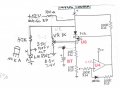
To adjust R13, it is easier to substitute a pot for Bt, VR, about 1k. A V supply of 9 to 12V in place of SP. Set VR to 8.3V, max charge V. Starting with R13 tap near ground, monitor output of U4, should be low = charging; inchease R13 untill U4 goes high. Lower VR untill U4 goes low, measure V of U6 D, hopefully is should be close to 7.4V. slightly lower than normal operating V; if high increase R15,[ temp sub pot, measure, replace with same value. As R13 & R15 interact, any change to R15 means repeating setup.
 

Attachments

Bernard

Joined Aug 7, 2008
5,784
LED ckt adjustment: With SP or simulated panel of +12V & 100 Ω series resistor connected to + side of 100μF, LED power buss, adjust VR1 to give 9V on power buss. Note that the red LED V reg, is to be replaced with LM336Z when available.
 

Thread Starter

jenovauh

Joined Jul 4, 2013
246
The shottky diode that I used is Central Semi. CMSH3-40, SM, for free so did not mind soldering on leads, 3A, 40V.5V drop; in DO41 pkg. same specs is NTE585 1A, or in DO27 [ like 1/2 W resistor] @ 3A, 40V, NTE586.
With just a little more V drop, you could use plain Si rectifiers like 1N400 series. Keep the one 1N914/ 1N4148.
Must have goofer on connecting LED ckt. to Bt ckt. On your first schematic just drop red line down to connect with first horizontal line, all grounds common.
When lines cross, I always assume no connection, but if it is a connection, it needs big black dot, or offset one line as on my origional drawing. Your schem. needs three big black dots as shown in red.
To adjust R13, it is easier to substitute a pot for Bt, VR, about 1k. A V supply of 9 to 12V in place of SP. Set VR to 8.3V, max charge V. Starting with R13 tap near ground, monitor output of U4, should be low = charging; inchease R13 untill U4 goes high. Lower VR untill U4 goes low, measure V of U6 D, hopefully is should be close to 7.4V. slightly lower than normal operating V; if high increase R15,[ temp sub pot, measure, replace with same value. As R13 & R15 interact, any change to R15 means repeating setup.
I will try to understand the changed as I am getting more and more confused. Anyway the NTE585 or NTE586 part is too expensive to purchase at my location, it is about $2.5 per pieces. Can I just use 1N914/ 1N4148 for all the diodes?

And also do you have any idea why the LEDs array circuit I tested with a 9V battery, the 47 Ohm 1W resistor got very hot after like 10 seconds. And around 20 seconds, it smoke too.

Base on your second drawing, do I need to remove U5?. I really could not figure out the whole schematic anymore as it is really getting confuse for my level of understanding. Hope you can paint a clearly picture for me to understand at my level.
 
Last edited:
Top