Need help, piggyback power source

Thread Starter

Afycsopo

Joined May 25, 2017
3
First I would like to apologize for my ignorance. I fully understand this is probably a bad idea. That's why I'm only asking in theory, not in practice. If I wanted to piggyback a USB port from the power INSIDE a power strip how would I do that? I looked inside one with USB ports and the board was simply wired to each side of the brass strips that run the length of the power strip. It was 22 gauge wire and there was a black one and a white one. If I took apart a USB charger and tried to power it up inside the power strip how could I do that? Again, I apologize for barging in here and asking this but I have searched for weeks to figure this out and I just can't get an answer for this. I've endured electricians making fun of me on their board because I don't know much about electricity. Of course, if I knew I wouldn't be asking. Anyway, I would appreciate your help. Thanks in advance

I guess I better add why I want to do this. There's always "that guy" who asks the questions. I'm making something to charge phones where the cord can't be stolen. (Unless they screw the bottom off the power strip). And yes I know they sell powerstrips with USB ports. I'm not interested at all in alternatives. I just want to know how to power a USB charger inside a power strip. Thanks.

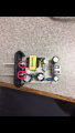
Here's what I'm working with.
IMG_3078.PNG IMG_3076.PNG
 

Thread Starter

Afycsopo

Joined May 25, 2017
3
I just got some information on how one company does it.

"The assembly techs will disassemble a USB charger and wire it direct to the main AC lines going into the power strip. They will also solder the wire from the USB cable directly to the output on the USB Adapter board."

Could somebody help me do that?
 

Reloadron

Joined Jan 15, 2015
7,517
"The assembly techs will disassemble a USB charger and wire it direct to the main AC lines going into the power strip. They will also solder the wire from the USB cable directly to the output on the USB Adapter board."
That pretty much sums it up. You would remove the remaining plastic from the USB charger you have and wire the AC mains prongs (removing the prongs) to the AC mains power. The problem you have is making things fit. The problem also being how to make the USB socket fit into the scheme. Another problem is you are working with mains which requires some degree of caution and safety practices so when this thing is assembled no mains power is exposed. If I were you I would find a suitable USB charger and literally glue the thing to the power strip. Epoxy it on the strip. Unless you remove an outlet or two from the inside of the strip I see no way to make things fit.

Ron
 

Thread Starter

Afycsopo

Joined May 25, 2017
3
First, thank you very much for your patience and your help. I'm a member of a forum where I'm considered an "expert" (everyone is an expert at something) and I encounter stupid questions all the time. But I do my best to answer them in a way that's not discouraging. Thanks again.

It actually does fit. And I'm able to leave the bottom half of the original casing on it to help secure it.

I understand the worry about it being too crowded and wires touching each other or touching something period. All I know to do is make sure nothing metal touches anything else that's metal.

I am wondering though about the attachment to the charger board. Please excuse my terminology because I'm sure I'm about to sound like a 2nd grader. The prongs fit into two metal arches on the side of the board. Would that be what I need to attach my wires to? That's what I circled in red.

And if so what in the world do I use to attach the wire to it?

And I will only need 2 wires and not 3 right?

Also, since the prongs are the same size and could be plugged into the outlet either way does that mean I can attach the wires to either side of the power strip's brass strips as long as one wire goes to each side?

The brass strips (I assume they're brass) have a handy little hole in them and it was really easy to attach a wire to them with a ring terminal.
 

Attachments

Reloadron

Joined Jan 15, 2015
7,517
Yes, where you have circled the two prongs I would remove the prongs and solder two wires. Those two wires would connect to your mains power. I would just solder two insulated wires at the points the prongs are tied. Yes, you only need to use those two points, only two wires. On the strip power in the green is ground, the black is Line (hot) and the white (Neutral). If your 5 Volt supply had one fat and one narrow blade the black would be connected to the narrow blade. The 5 Volt supply looks to just use a small transformer to reduce the mains voltage and some electronics to get the DC 5 Volt output.

Ron
 
Top