Need help on PWM motor control

Thread Starter

mezzmen

Joined Jun 27, 2017
18
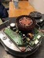
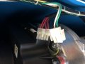
Hi, I’m currently taking electronics classes but still have a lot to learn. I have fan that is for a boiler at work it has line voltage and pwm motor controlled being controlled by the boilers computer. It’s a newer style boiler. The old fan started sparking and Looks like some caps blew on the circuit on the fan. I can’t figure out whats wrong. I bought a new fan and ran it for a couple mintutes and it looks like through the fins , a cap is leaking right away. Here is a picture of of the connecter and little schematic of the inputs and outputs.With the connector unplug I read 60v to chassis ground ac at the wire labeled pwm ground. With it disconnected should that wire read zero??
does anybody have information on this type of pwm controlled motor works? I can’t find any information myself. Thank you for any suggestions
 

Attachments

MaxHeadRoom

Joined Jul 18, 2013
28,617
Those motors are generally ECM (electronically commutated) BLDC motors, the internal control board does the commutation and it relies on 4,5,6,7 to control.
You may have to see where these 4 connections comes from to analyze what you should be seeing on them.
Are you saying you changed the fan and the cap is leaking right away?
If electrolytic it could be getting a AC signal instead of DC maybe.
Max..
 

Thread Starter

mezzmen

Joined Jun 27, 2017
18
Thanks for your reply. yeah after a couple minutes I seen through the plastic cover fins one of the smaller electrolyic capacitors has a black glob next to it. Before the old one failed I was doing something on the boiler not related to that fan so it was off for a couple days and when I turned it on it started sparking bad after 30 seconds of it being on. I’m thinking of getting a oscilloscope and probing those four wires to see what is going on. I’m not to sure what I’m doing though. I put a dmm on on those leads and they read 60v ac and when I switched to dc it read the same voltage. I’m just lost
 

MaxHeadRoom

Joined Jul 18, 2013
28,617
Are you sure the 'black blob' is not RTV to secure the cap from vibration?
Can you tell the origin of the 4 wires?
Has the new fan quit on you?
Max.
 

Thread Starter

mezzmen

Joined Jun 27, 2017
18
I am not sure if it is RTV. I need to peak in there when I get back to it to see wha it looks . It did not fail. I just unplugged it when I looked and it looked like that cap was leaking. the 4 wires go to the boiler controller computer. It’s the connector to that fan to that controller.
 

Thread Starter

mezzmen

Joined Jun 27, 2017
18
Yeah it works. I unplugged it though,since I think it was going to get worse when I seen that blob. , maybe I’ll just let it run and see if it starts sparking like the old one. The problem is the fan cost 2 grand
 

jeffl_2

Joined Sep 17, 2013
74
The measurement of voltage to chassis ground is probably meaningless, since that connection is usually concerned with issues like shock safety and control of RF noise. It might be possible to find a "meaningful" ground connection but you need to be careful that in connecting to it you aren't making a direct connection to one side of the AC line, and therefore setting up to get a nasty shock and possibly burn up what's left of the control circuit. The real problem here is the tiny fraction of a schematic that you provide doesn't really allow the analysis of critical issues like this. Without more circuit information the only way to safely connect to that circuit is by plugging it all in through an isolation transformer rated at the correct voltage and sufficient current to correctly power the unit. Also I have no idea what the issue with the capacitor is because a "PWM circuit" doesn't by itself imply that a capacitor is present, or its function. Since there are only three wires actually connected to the motor it has to be a simple single circuit device with possibly a feedback speed control. It's POSSIBLE to use PWM for a single-phase induction motor but they aren't used that way so it appears to be a simple brushed-type DC motor (could be wrong but I doubt it), NOT a BLDC because that would be 3 wires exclusive of speed monitor. I can't even figure out why PWM is needed if the temperature sensor is only "on-off" unless there's also a manual fan speed control which is not shown. Now why a fractional HP DC motor should cost 2 grand (if that doesn't include anything except for the impeller and scroll wheel) is beyond me, I suspect you were ripped off. If you REALLY want to analyze a PWM control circuit, having a portable oscilloscope wouldn't hurt so you could see the duty cycle. The biggest help would be more of the schematic, even if the PWM is encapsulated in an MCU there would still be "clues" (like its part number!!) and other necessary components that would allow us to help you a lot more.
 

Thread Starter

mezzmen

Joined Jun 27, 2017
18
Thank you very much for all the information. That’s a lot to take in. I need to read more on how these Motors work. I learned what pwm is in class but not applying it to something like this. Maybe in a later class. The good news is that black glob looks like it’s there to keep the capacitor in place and not leaking from the cap . And I plugged everything back in and has been running fine for 4 hours. I really want to learn more about how this all works with the pwm control. Its varies it’s speed accordingly but if I were to unplug those control wires it will run full speed with the line voltage connected .2 grand was a cheap price on this. Compared to 3k from other vendors. This blower is made in Germany only for selected boilers. So they jack up the price knowing you don’t have any other option. Here is a picture of the circuit from the blower that sparked up. Here is a Schematic for that blower. Maybe this can give you more information on it
 

Attachments

MaxHeadRoom

Joined Jul 18, 2013
28,617
The measurement of voltage to chassis ground is probably meaningless, since that connection is usually concerned with issues like shock safety and control of RF noise. It might be possible to find a "meaningful" ground connection but you need to be careful that in connecting to it you aren't making a direct connection to one side of the AC line, and therefore setting up to get a nasty shock and possibly burn up what's left of the control circuit. The real problem here is the tiny fraction of a schematic that you provide doesn't really allow the analysis of critical issues like this. Without more circuit information the only way to safely connect to that circuit is by plugging it all in through an isolation transformer rated at the correct voltage and sufficient current to correctly power the unit. Also I have no idea what the issue with the capacitor is because a "PWM circuit" doesn't by itself imply that a capacitor is present, or its function. Since there are only three wires actually connected to the motor it has to be a simple single circuit device with possibly a feedback speed control. It's POSSIBLE to use PWM for a single-phase induction motor but they aren't used that way so it appears to be a simple brushed-type DC motor (could be wrong but I doubt it), NOT a BLDC because that would be 3 wires exclusive of speed monitor. I can't even figure out why PWM is needed if the temperature sensor is only "on-off" unless there's also a manual fan speed control which is not shown. Now why a fractional HP DC motor should cost 2 grand (if that doesn't include anything except for the impeller and scroll wheel) is beyond me, I suspect you were ripped off. If you REALLY want to analyze a PWM control circuit, having a portable oscilloscope wouldn't hurt so you could see the duty cycle. The biggest help would be more of the schematic, even if the PWM is encapsulated in an MCU there would still be "clues" (like its part number!!) and other necessary components that would allow us to help you a lot more.
I dearly wish posters would use paragraphs, Much easier to read! :rolleyes:
Max.
 

MaxHeadRoom

Joined Jul 18, 2013
28,617
Thank you very much for all the information. I need to read more on how these Motors work. I learned what pwm is in class but not applying it to something like this. Maybe in a later class. The good news is that black glob looks like it’s there to keep the capacitor in place and not leaking from the cap .
Figured it was a vibration deterent.
Here is some clue on the ECM BLDC motor controller.
If yours has Hall sensing then that is not normal for blower ECM.
Max.
 

Attachments

jeffl_2

Joined Sep 17, 2013
74
It just occurred to me, there could be one other interpretation. The motor could conceivably be of a BLDC variety, but there would need to be a "commutating controller" INSIDE the motor housing, where part of the commutation of the phases would be individual PWM control and sequencing of each phase. And then the speed control of the motor would be imposed by a digital signal from a SECOND external PWM applied through the line labeled "input" (and likely the frequency of the second PWM is specified as different from the commutating frequency). Or maybe the second digital signal as used is effectively just "on-off". I would comment that the trend has been in the opposite direction, towards puting the controller OUTSIDE the motor enclosure, because the interface nowadays is only three wires, and that way the controller and motor can be replaced/diagnosed separately, but if this is happening in Europe the trends might be quite different. I don't know if that's what's going on but clearly if the bulk of the control circuitry is inside the motor then it's next to impossible to troubleshoot any electronics, but then again maybe that's exactly what the manufacturer wants, and it helps explain why the motor is so pricey. Sorry I missed that the first time!
 

Thread Starter

mezzmen

Joined Jun 27, 2017
18
Thanks for the information, this is definitely something I need to learn more about. The circuit on top of the motor seems not to be troubleshooted ,since the plastic cover I took off,is not held on by nuts, instead it’s some kind of pressed in locking ring that I had to bend and snip
 

MaxHeadRoom

Joined Jul 18, 2013
28,617
The motor could conceivably be of a BLDC variety, but there would need to be a "commutating controller" INSIDE the motor housing, where part of the commutation of the phases would be individual PWM control and sequencing of each phase. And
The trend in N.A. at least is that the typical HVAC ECM motor has the electronics internal, the commutation is by sensorless current sensing. See attachment in post #11.
Max.
 
Top