Another question... do you think I should be using an op amp than can handle a higher output current? I know the required current is an unknown so its kind of a shot in the dark... or should this suffice?
Are you joking? You want me to tell you what I guess somebody might want after that somebody did not say they need anything better? You guess. Then run all that math again for protection of the new op-amp.
Are you joking? You want me to tell you what I guess somebody might want after that somebody did not say they need anything better? You guess. Then run all that math again for protection of the new op-amp.
I just don't know what a typical value is for something like this is all. From what I can tell most op-amps are in the 15ma - 35ma range. If 25ma doesn't seem right I can try and find a different op-amp and it would be a good exercise for me to go through the math again. I would prefer not to change it if I don't have to and continue using the current one. It seems like there will be a lot of improvements already from the mentioned changes.
Would this be a safer/robust choice? If you agree I will go through the math again for this op-amp and will post an updated schematic. Out of around 20 circuit boards, 2 of them have had the op-amp fail, so I'm thinking between one that can handle higher output amperage, plus the added protection it would be good to go?
Also, just to let you know, I am a software engineer, not an EE... so I only know enough to be dangerous with it, I don't have the comprehensive knowledge. So that might be why some of my questions/logic with this stuff does not make a lot of sense, still learning the process and how this stuff works.
Ok I was able to measure the amps by just cutting a spare cable and measuring it from there. The machine draws between 150uA and 10uA (0.15mA and 0.01mA)depending on the potentiometer position (my device is basically going in place of the potentiometer to control the machine). So this is basically nothing? So there is no chance that the machine is drawing too much current and overloading the op-amp then correct?
If the machine has no fault there's no way that current can overload an opamp output. So if you're frying opamps either there is a machine fault, or voltage spikes from somewhere are doing the damage.
Ok I was able to measure the amps by just cutting a spare cable and measuring it from there. The machine draws between 150uA and 10uA (0.15mA and 0.01mA)depending on the potentiometer position (my device is basically going in place of the potentiometer to control the machine). So this is basically nothing? So there is no chance that the machine is drawing too much current and overloading the op-amp then correct?
Cutting a SPARE cable? How exactly were you measuring current?
To measure current, move the red test lead on your meter to the "amps" input, set your meter to DC amps (some fluke meters use the same switch position as AC amps but you have to push the function button to get DC amps to read instead of AC default.
Then connect meter in series with your circuit. That is, cut the cable or insert between a de-soldered input wire and the pcb hole where the wire was.
Congratulations. You have discovered that the OPA171 that you already have installed can deliver 100 times as much current as needed, even with safety considerations on every pin that is connected to anything.
Congratulations. You have discovered that the OPA171 that you already have installed can deliver 100 times as much current as needed, even with safety considerations on every pin that is connected to anything.
The diodes are escape routes for any external current that might try to enter the output of the op-amp. If an offending voltage is high (positive), it gets directed to the power supply to be absorbed or discarded through the zener. If a voltage arrives that is more negative than ground, it is redirected to ground.
The inputs of the op-amp are already protected with diodes. You merely have to limit offending current to 10 ma to keep it within the capabilities of the chip's self defense circuits.
So I made those changes and everything is working great now, thanks again for all of your help.
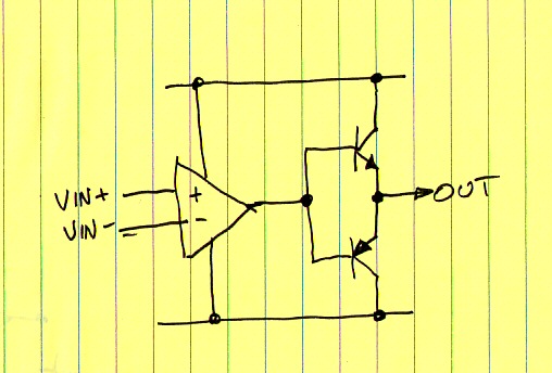
I would like to make a version that can handle up to 1 amp on the op amp output. It seems this is doeable with using transistors? Is this on the right track? Is there anything I should be aware of?
1) You don't need a circuit that can deliver 1 amp into a 150 microamp load.
2) This is a completely different circuit and should have a new Thread.
3) The circuit you drew is for use with a bi-polar power supply. You only need one transistor when you only have one voltage supply.

 Facebook
 Google
 GitHub
 Linkedin