 Facebook
 Google
 GitHub
 Linkedin
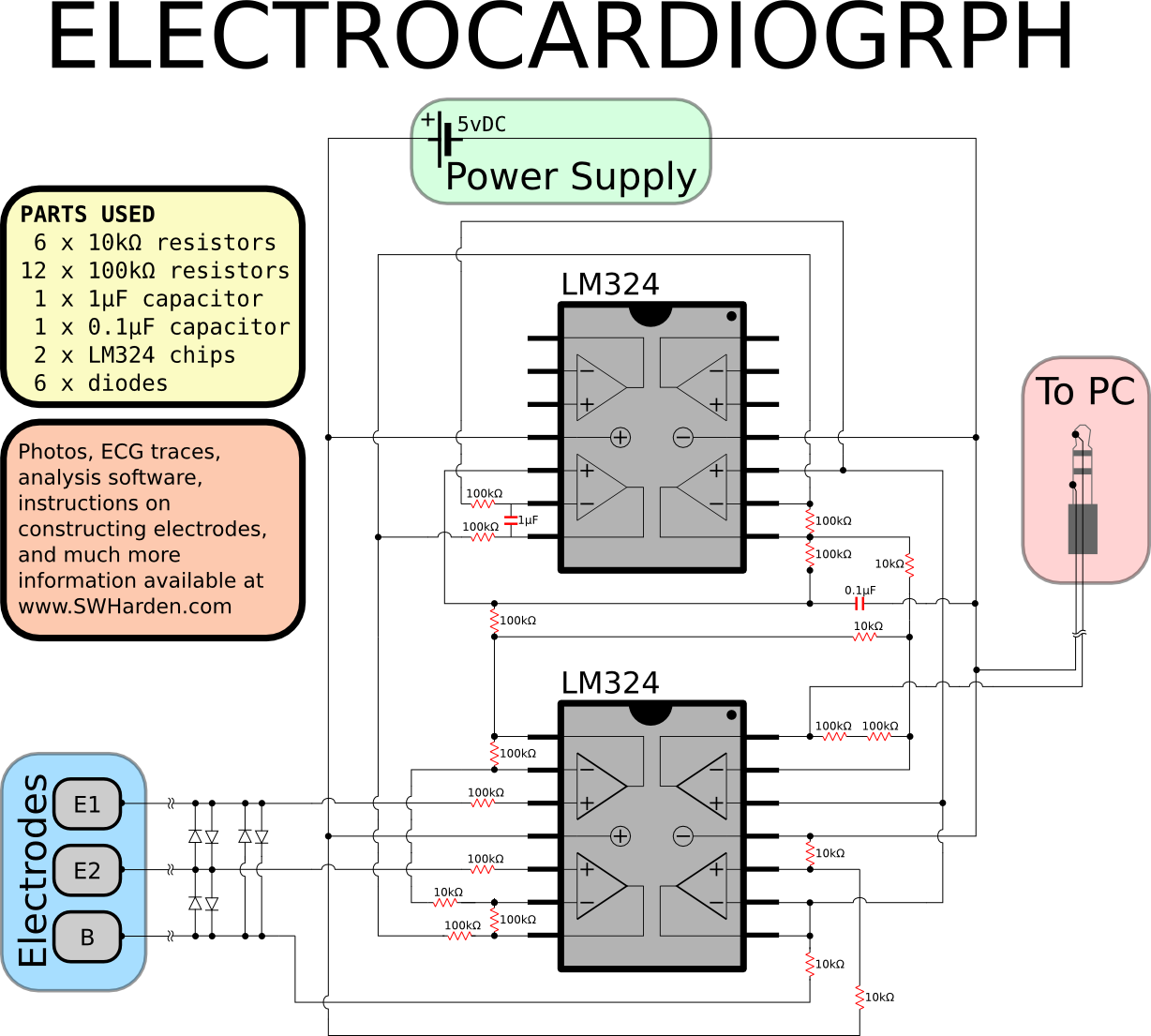
Hi all, i have some doubt for this Circuit Diagram's filter.
1) from the circuit diagram, can anyone help me calcuate the cut of frequency of the both filter and show me the calculations ? as i don really understand what filter is that. from what i know, both of them are RC low pass filter.
2) is that IIR filter or FIR filter ?
3) are both the filter RC low pass ?
4) where is the refrence point for this circuit? is this circuit grounded ?
sorry for so many questions.
and thanks for those who help!

 .. can u please assist me ? thanks!


